 |
Depending on how you are going to use the MDC box you may have to change the internal jumper settings and fuse position. As standard the MDC box comes configured for 24V DC power input on the green connector and gives a 24V output for the Moxa unit and a 5V output for the barcode reader. If you are not going to use a barcode reader or you want to use a 24V source from a Fanuc RS-232 connector YOU MUST open the box and change the settings.
|
To adjust the links on a MDC unit the top of the box has to be removed. At the ends of the box near each corner there is a small rectangular hole. Insert a small screwdriver into each hole in turn while gently easing the box apart. The box should then come apart revealing the circuit board inside as below.
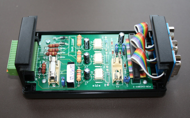 |
There are three links (LK1, LK2 and LK3), two fuse positions (F1 and F2) and a jumper (J3) on the MDC circuit boards (check the Part number is PCB- CNC003-2). These links are used to control how the unit routes RS-232 data, 24V power in and out and 5V power out for a barcode reader.
If the MDC unit is being used with a Moxa serial hub that is powered from the machine (using a Moxa PSU plugged into 110-24V socket) and there is no requirement for a barcode reader, then there is no need to connect 24V to the MDC box (+24V and 0V in connections).
If the MDC unit has to supply power to a barcode reader (+5V out) or a Moxa unit (+24V out) it will require a 24V supply connected from the machine.
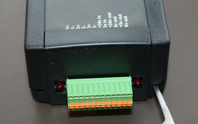
This 24V input supply can be connected to the +24V in and 0V in sockets on the green connector, or in the case of most Fanuc controls from pin 25 on the machine's RS-232 connector. Using pin 25 on the Fanuc control can cause occasional problems with some Fanuc based controls, in which case using the machines 24V supply is the better option.
We supply the MDC unit configured for 24V supply on the green connector and 5V output for a barcode reader. This is done as follows. The 1Amp fuse is placed in F1 to use power from the green connector as the picture below.
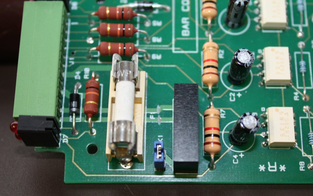 |
If the MDC unit is being used to power a barcode reader make sure link LK1 is in place, this sends the 24V input into the 5V converter (the black component beside the link) used to power the barcode reader.
If the MDC unit is not being used to provide power for the barcode reader LK1 MUST be removed to prevent damage to the 5V converter.
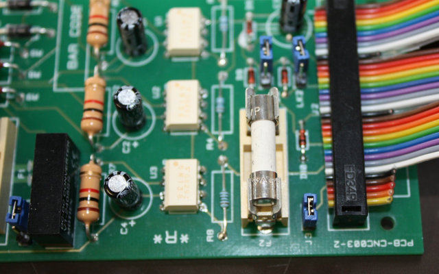 |
If you want to power the MDC box from the Fanuc RS-232 connector you need to make up a special RS-232 cable as below. This cable takes the 24V from the Fanuc pin 25 and supplies 24V to pin 9 on the M/C connection on the MDC box. The fuse has to be moved to fuse holder F2 and the link J3 should be closed as the picture above.
Again if the MDC box is being used to power a barcode reader make sure link LK1 is in place (see section above), this controls the 24V input into the DC/DC converter used to provide 5V for the barcode reader. If the MDC unit is not being used to provide power for the barcode reader LK1 MUST be disconnected to prevent damage to the 5V converter.
|
9 way M/C connector on MDC box |
25 way Fanuc on Machine | |
| 3 | brown | 3 |
| 2 | red | 2 |
| 7 | blue | 5 |
| 8 | white | 4 |
| 5 | black | 7 |
| 1 | yellow | 1 |
| 9 | orange | 25 |
| 6,8,20 Linked |
The MDC unit is designed to connect to a serial hub (wired or wireless) inside the control cabinet of a machine tool (e.g. Moxa W2150+), by a short ribbon cable. In some instances this is not possible, either the serial hub is not mounted in the machine cabinet, or the machine is cabled to a remote hub that serves multiple machines. The RS-232 signals inside the MDC units have signal diodes in them to avoid RS-232 conflicts between the barcode reader and machine tool interfaces.
In some cases, if the serial hub is some distance from the machine, this can cause problems with signal strength on the RS-232 signal line out of the MDC unit back to the serial hub.
You will notice that the RS-232 data from the machine is corrupt. In most cases closing Link LK2 resolves the problem with the machine RS-232 signal, in very rare cases this also affects the barcode reader signal, in which case LK3 should be closed as well.
This corruption can also be caused by poor machine control earthing and the installer may need to consider opto-isolation between the MDC unit and the machine control.