 |
|
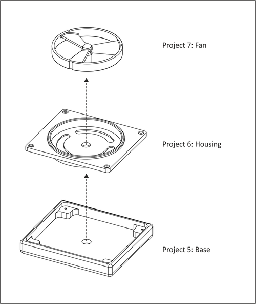
Figure A.14: Fan Assembly, Projects 5-7 |
Projects 5, 6 and 7 form a simple assembly. The parts must be machined to the specified tolerances in order to fit together.
|
|
Figure A.14: Fan Assembly, Projects 5-7 |
This project teaches the following skills:
 |
|
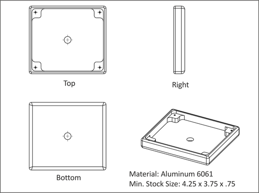
Figure A.15: Project-5, Base |
Grip the sawed stock as shown in figure in Table A.2. Set the XY-datum from the upper-left corner of the stock. Make sure there is sufficient stock so that finish tool paths remove material all around the part (typically .01-.05 inches from the stock corner). Set the Z-datum so that the facing operation removes material from the face of the part (typically .01 in below the face of the sawed stock).
Machine the part using the processes and parameters in Table A.2. If needed, select tools, speeds and feeds compatible with your machine.
|
Base: Job-1 Setup | ||||
|
| ||||
|
G54 Datum: Upper-Left corner of sawed stock. | ||||
|
Op-1 Face |
Tool (in) .375 End Mill 2-Flute |
Speed (rpm) 8150 |
Feed XY (ipm) 33. |
Feed Z (ipm) 15. |
|
Use a stubby end mill to reduce chatter (flute length=.625). Stepover=.20, Take a Z finish pass of .005 to ensure a good surface finish. | ||||
|
Op-2 2D Contour |
Tool (in) .375 End Mill 2-Flute |
Speed (rpm) 8150 |
Feed XY (ipm) 33. |
Feed Z (ipm) 15. |
|
Contour OD. Rough Stepover =.2, Stepdown=.2. Finish XY=.01, No Finish Z needed. Number of rough passes depends on stock size. | ||||
|
Op-3 2D Pocket |
Tool (in) .375 End Mill 2-Flute |
Speed (rpm) 8150 |
Feed XY (ipm) 33. |
Feed Z (ipm) 15. |
|
Rough and finish pocket with islands. Rough Stepover =.2, Stepdown=.2. Finish XY=.01, Finish Z=.005 | ||||
|
Op-4 2D Contour |
Tool (in) .375 End Mill 2-Flute |
Speed (rpm) 8150 |
Feed XY (ipm) 33. |
Feed Z (ipm) 10. |
|
Contour the hole in the center of the pocket with helical entry. Finish XY=.01, Finish Z -.010 below bottom so no flashing is left after facing opposite side. | ||||
|
Op-5 2D Contour |
Tool (in) .125 Center Drill, 90Deg |
Speed (rpm) 5000 |
Feed XY (ipm) 40. |
Feed Z (ipm) 20. |
|
De-burr top edges by creating a .07 chamfer. Use line/arc lead in/out. | ||||
|
Op-6 CTR Drill |
Tool (in) .125 Center Drill, 90Deg |
Speed (rpm) 6100 |
Feed XY (ipm) N/A |
Feed Z (ipm) 12. |
|
Center drill the four #2-56 holes. Dwell .5 seconds. | ||||
|
Op-7 Peck Drill |
Tool (in) Drill .07 Dia. (#50) |
Speed (rpm) 10000 |
Peck Inc. (in) .035 |
Feed Z (ipm) 20. |
|
Peck drill four #2-56 holes. | ||||
|
Op-8 Rigid Tap |
Tool (inch) #2-56 Tap |
Speed (rpm) 4300 |
Peck Inc. N/A |
Feed Z (ipm) 76.786 |
|
Tap four holes to depth Z-.26 below top of boss. If your machine does not support rigid tapping, tap by hand after job is complete. | ||||
|
Op-9 Contour |
Tool (in) .115x.093 Radius Mill |
Speed (rpm) 6640 |
Feed XY (ipm) 40. |
Feed Z (ipm) 20. |
|
Use corner round tool to create a fillet on outside of the part. Take two finish passes (one spring pass) to produce a very good surface finish. | ||||
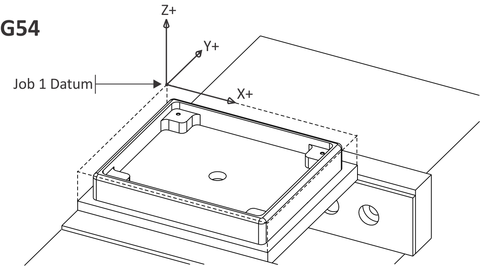
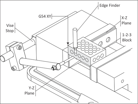
The XY datum for Job 2 could be set at the center of the through hole using a coaxial indicator, dial indicator, or machine part probe. The method illustrated here shows how to set the datum using a vise stop and 1-2-3 block.
Program X0 is found using an edge finder to locate the left edge of the 1-2-3 block (YZ Data Reference Frame). Set the Fixture Offset X-vale as the centerline of the left 1-2-3 block edge.
Program Y0 is found using an edge finder to locate the fixed vise jaw (XZ Data Reference Frame). Set the Fixture Offset Y-value as the centerline back 1-2-3 block edge.
Step-by-step instructions for setting the Fixture Offset XY using an edge finder are found in Chapter 6: CNC Operation.
|
Many CNC machines are now equipped with a Part Probe. This instrument is gripped in machine spindle and communicates with CNC control when the probe stylus touches against a surface. Part probes greatly speed and simplify setting fixture offsets. To learn more refer to the documentation included with your part probe or search YouTube© for videos on the topic. |
 |
|
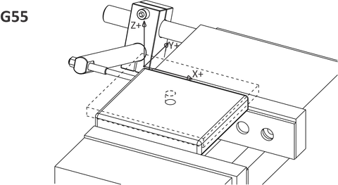
Figure A.16: Set G54 XY Using A 1-2-3 Block |
G54 Z could be set at the top of the vise parallels. If using this method, set the tool rapid and clearance heights sufficient to avoid colliding with the part, vise, and fixture.
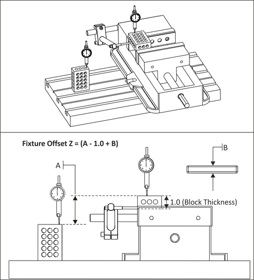
The approach described here sets G54 Z to the value of the face of the finished part for Job 2. To find the distance from the top of a 1-2-3 block to the top of the finished part use this formula:
Fixture Offset Z = (A - 1.0 + B)
As illustrated in Figure A.17, A is the incremental distance from the top of a 1-2-3 block resting on the table to the top of a 1-2-3 block set in the vise. B is the finished thickness of the part. The value 1.0 is the thickness of the 1-2-3 block.
Stated as a word problem, this formula reads, "The Fixture Offset Z is the distance from tool setting point to the bottom of the 1-2-3 block, plus the thickness of the finished part".
|
The process of setting the fixture offset is described in detail in Chapter 6: CNC Operation. |
 |
|
Figure A.17: Set Z Datum |
Clean the work area and set the part finished upside-down in the vise. Slide the part left-right and apply pressure so it rests firmly against the fixed vise jaw and vise stop as shown in figure in Table A.3 and close the vise jaws firmly. This establishes the XY datum. Next, tap the part down with a rubber mallet to ensure it is flat against the parallels and close the jaws tightly.
When making multiple parts, mark the vise with marker or use a torque wrench to ensure each part is gripped with the same vise force.
|
Base: Job-2 Setup | ||||
|
| ||||
|
G54 Datum: Upper-left corner of finished part face. | ||||
|
Op-1 2D Contour |
Tool (inch) .375 End Mill 2-Flute |
Speed (rpm) 9800 |
Feed XY (ipm) 68. |
Feed Z (ipm) 30. |
|
Contour OD leaving .010 in XY Stock. This cut is used to clear excess material from the part so the corner round tool will not engage an excessive amount of material. | ||||
|
Op-2 Face |
Tool (inch) .375 End Mill 2-Flute |
Speed (rpm) 9800 |
Feed XY (ipm) 68. |
Feed Z (ipm) 30. |
|
Face part using a stepover of .20 in and stepdown of .10 in. The number of Z-roughing passes required depends on the amount of material remaining on part. Finish pass should be no greater than .005 in to yield a good finish. | ||||
|
Op-3 2D Contour |
Tool (inch) .115x.093 Radius Mill |
Speed (rpm) 5000 |
Feed XY (ipm) 40. |
Feed Z (ipm) 20. |
|
Use corner round tool to create fillet on outside of part. Take two finish passes to produce a very good surface finish. | ||||
|
Op-4 2D Contour |
Tool (inch) .25 Spot Drill 100 degree |
Speed (rpm) 8900 |
Feed XY (ipm) 40. |
Feed Z (ipm) 10. |
|
Engrave lettering. Depth = Z-.005 in | ||||