 |
|
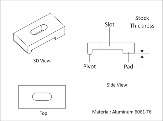
Figure A.23: Custom Clamp Features |
Clamps are a very common work holding device. Many sizes and styles of clamps are commercially available. This project shows how to machine custom size aluminum clamps that will be used to hold the part in Project 10. This project teaches the following skills:
Figure A.23 shows a typical custom clamp. The pivot rests on the fixture plate and allows the clamp to freely rotate. The slot is slightly wider than the bolt used to secure the clamp and allows the clamp to be positioned. The pad that rests on the stock is offset by the thickness of the material to be gripped.
If the part being held by the clamps is aluminum, use aluminum clamps to reduce marring of the part. If using steel clamps to hold softer metals, consider inserting an aluminum pad between the pad and the part.
|
|
Figure A.23: Custom Clamp Features |
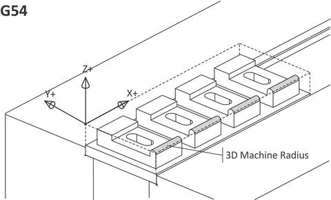
Figure in Table A.8 below shows how all clamps can be machined from a single bar of stock. Machine the pivot radius using a corner round tool, or 3D surface machine it with a flat cutter.
Once the part has been completed as shown in this illustration, flip it over in the vise and machine the top surface to free the parts.
|
Fan: Job-2 Setup | |
|
| |
|
Datum: Upper-left corner of stock. | |
|
Op-1 Face |
Face top of pad, slot and radii. |
|
Op-2 2D Contour |
Cut around perimeter of all parts. |
|
Op-3 Slot Mill |
Machine slots. |
|
Op-4 3D Mill |
3D finish the radii. Surface finish is not important. |
|
Op-5 Face |
Flip part over and face to free all clamps from bar stock. |