 |
|
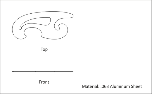
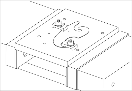
Figure A.25: French Curve |
This project teaches the following skills:
|
|
Figure A.25: French Curve |
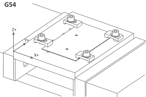
Plate parts can present unique work holding challenges. Thin and flexible material tends to be lifted and torn by the cutter. This exercise uses the fixture plate created in Project 9 and works with parts that have good rigidity.
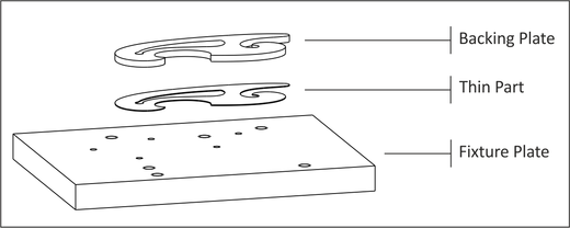
This same process can be used with very thin and flexible parts that would normally require stamping or laser cutting by sandwiching the material between a backing plate and the fixture plate, as shown in Figure A.26 below.
 |
|
Figure A.26: Thin Part with Backing Plate (Finished) |
The following instructions show how to use the fixture plate created in Project 9 to machine a sheet metal part.
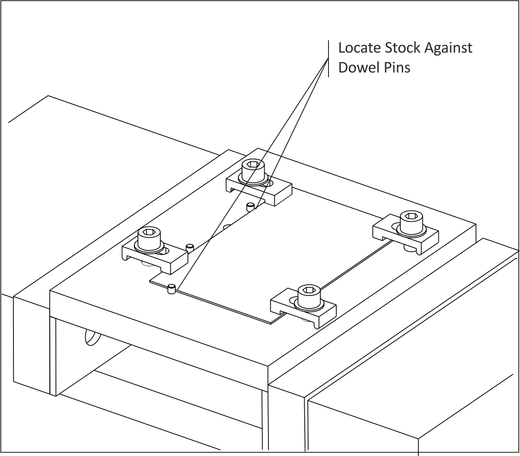
Use the dowels pins to locate the stock material as shown in Figure A.27 and tighten the clamp bolts firmly.
If using steel clamps on aluminum or other soft material, adjust clamp pressure carefully and consider placing a piece of aluminum between the clamp and part to prevent marring.
 |
|
Figure A.27: Clamp Part |
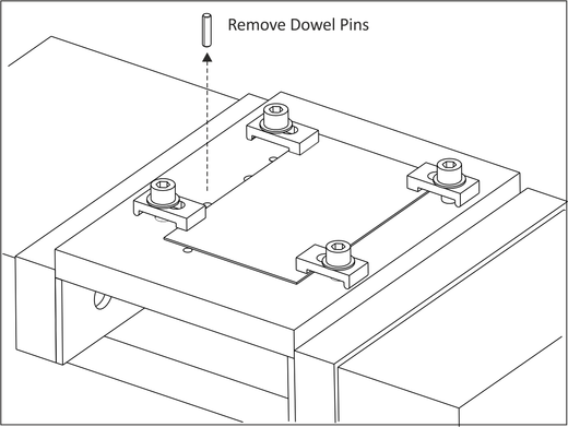
Any contact between a hardened dowel pin and tool will destroy the tool. Remove the dowel after clamping if there is any chance the tool could come in contact with it.
 |
|
Figure A.28: Remove Dowel Pins |
Drill Holes for the #6-40 screws that will secure the part after the stock being gripped by the clamps is cut away. The drill depth should be just enough so the shoulder clears the bottom of the part, but does not cut deep into the threads in the fixture plate.
|
French Curve: Job-1 Setup | ||||
|
| ||||
|
Datum: Use same datum as fixture plate. | ||||
|
Op-1 CTR Drill |
Tool (in) .25 Ctr Drill |
Speed (rpm) 1800 |
Feed XY (ipm) 18.0 |
Feed Z (ipm) 9.0 |
|
Rough XY (in) 1.0 |
Rough Z (in) .25 |
Feed XY (ipm) 1.0 |
Finish Z (in) .005 | |
|
Op-2 Drill |
Tool (in) .156 (5/32) Drill |
Speed (rpm) 3200 |
Feed XY (ipm) 36.0 |
Feed Z (ipm) 18.0 |
 |
|
Figure A.29: Install Bolts |
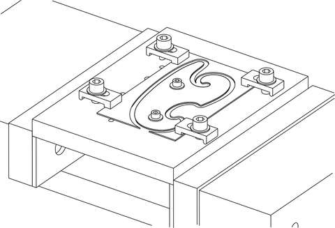
Cut the outside profile of the part as shown in the figure in Table A.11.
|
French Curve: Job-2 Setup | ||||
|
| ||||
|
Op-1 Contour |
Tool (inch) 0.25 End Mill |
Speed (rpm) 1800 |
Feed XY (ipm) 18.0 |
Feed Z (ipm) 9.0 |
|
Rough XY (in) .005 |
Rough Z (in) 0. |
Finish XY (in) .005 |
Finish Z (in) -.005 | |
|
Machine the OD taking one rough and one finish pass. Start the tool in an area where it is away from the clamps, and use line/arc lead in/out. Cut into the fixture slightly so there is no flashing on the bottom of the part. | ||||
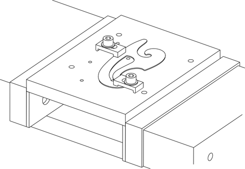
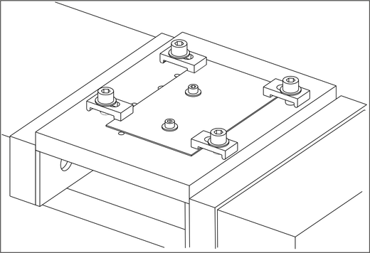
First move two of the clamps to the alternate positions shown so they secure the OD of the part. Then remove the hold down bolts so the ID of the part can be machined.
Be careful when tightening the clamp bolts. The part is thin and excess pressure might cause the part to deform. Of course, insufficient gripping force might allow the part to shift under the cutting forces and ruin the part. Using the custom clamps (Project 8) machined for this part maximize the grip surface area.
 |
|
Figure A.30: Move Clamps |
Machine the ID Profile to complete the part.
|
French Curve: Job-3 Setup | ||||
|
| ||||
|
Op-1 Contour |
Tool (in) 0.25 End Mill |
Speed (rpm) 1800 |
Feed XY (ipm) 18.0 |
Feed Z (ipm) 9.0 |
|
Rough XY (in) 1.0 |
Rough Z (in) .25 |
Feed XY (ipm) 1.0 |
Finish Z (in) .005 | |
|
Stock to Leave XY (in) 0.0 |
Stock to Leave Z (in) 0.0 | |||
|
To observe the effects of data starvation, set the tool length offset so the tool runs above the part. Run the program, increasing feed rate until the machine begins to shudder. Notice that the actual machine feed rate is less than the programmed feed rate. The feed rate at which this occurs depends on the block execution time of the machine tool. Reduce or eliminate data starving by reducing the feed rate at the machine, or by using the tool path filter function in the CAD/CAM software. |