 |
|
Figure 4.7: Work Coordinate System (WCS) |
Obviously it would be difficult to write a CNC program in relation to Machine Coordinates. The home position is far away from the table, so values in the CNC program would be large and have no easily recognized relation to the part model. To make programming and setting up the CNC easier, a Work Coordinate System (WCS) is established for each CNC program.
The WCS is a point selected by the CNC programmer on the part, stock or fixture. While the WCS can be the same as the part origin in CAD, it does not have to be. While it can be located anywhere in the machine envelope, its selection requires careful consideration.
For example, Figure 4.7 shows a part gripped in a vise. The outside dimensions of the part have already been milled to size on a manual machine before being set on the CNC machine.
The CNC is used to make the holes, pockets, and slot in this part. The WCS is located in the upper-left corner of the block. This corner is easily found using an Edge Finder or Probe (Chapter 6).
|
|
Figure 4.7: Work Coordinate System (WCS) |
The following example shows why and how the WCS is set up a typical part that is machined on multiple sides by gripping in a vise. This is one of the most common ways to hold a part. Pay particular attention how the part is rotated between jobs.
The term Job means a unique machining setup on the machine. For example, a part that requires the part to be moved or rotated three times on the CNC is said to be composed of three jobs, one for each setup.
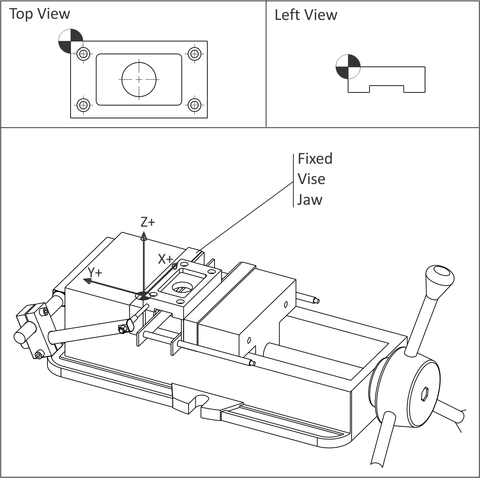
Figure 4.8 shows a part gripped in a six inch wide precision CNC vise. The outside shape of this part was machined to size on a manual mill before being set on the CNC machine. The CNC is used to create the holes, pockets, and slot on this block.
 |
|
Figure 4.8: Tool Length Offset Example (Job 1) |
Before clamping the part, the vise is aligned and bolted to the machine table. This assures the part WCS X-axis is aligned with the machine X-axis.
Parallels (precision ground rails) are used to support the part. These ensure the XY-Plane of the part is parallel to the machine table XY-Plane.
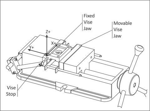
The left face of the part rests against a Vise Stop. The Vise Stop establishes the X-axis origin. As new parts are loaded into the vise, the operator slides them against the vise stop. This ensures all parts are loaded into the exact same position each time.
Because the edges of the block are already milled, the WCS XY location is easily found using an Edge Finder (Chapter 6: Set Fixture Offset XY) or part probe.
The vise has two jaws; a fixed back jaw a front jaw that can close and open to grip or release the part. Because the location of the moving jaw varies depending how much force the operator uses, it is best to locate the WCS in reference to the fixed jaw. The fixed jaw position is not significantly affected by clamping force.
Notice that, because the fixed vise jaw does not move regardless of how tightly the vise is closed, the WCS Y-origin does not change. In other words, the Y-origin is repeatable. The concept of repeatability is essential to precision machining. If the datum shifts for any reason, it is impossible to make any two parts exactly alike.
|
When using a vise, locate the WCS so the part lies in the forth quadrant: resting the Y-datum (XZ Plane) against the fixed vise jaw. |
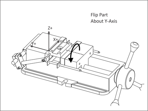
After the pocket, holes, and through round hole are machined on the first side of the part, the part is flipped over in the vise to create the slot. Whether a new WCS must be defined, and how the part is flipped, depends on the part geometry and type of setup.
As shown in Figure 4.9, because the outside dimensions of the part were established prior to machining, and because the part is flipped 180 degrees, the location of the WCS does not change. Therefore, there is no need to define a new WCS to machine the slot. Fixture Offset G54 can be used to machine both sides.
However, how the part is turned over does matter because of how a vise works. As mentioned earlier, a vise exerts a tremendous amount of clamping force (up to 6 or more) and so the actual position of the moving vise jaw depends on how tightly the vise is closed.
This variability is so large that it is common practice to mark the closed position of the handle with a black marker or use a torque wrench to ensure the clamping pressure is consistent between parts. Vise force can even significantly deform thin parts if excessive force is applied.
 |
|
Figure 4.9: WCS (Job 2) |
By flipping the part about the Y-axis, the same edge of the part (XZ Plane) rests against the fixed jaw. Since this position does change based on clamping force, and because the vise stop is also unaffected by clamping force, the WCS for Job 2 is also repeatable.
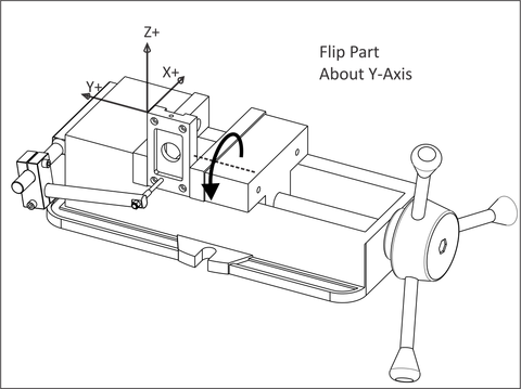
Drilling the hole in the side of the part means turning it again to stand on end, as shown in Figure 4.10. Again, rotate the part about the Y-axis so that the Y-origin of the WCS (XZ reference) plane does not shift or change based on clamping force.
Notice that the WCS used in Job 1 and 2 cannot be used because the part standing on end is much taller. A new Fixture Offset is defined (G55) to shift the datum to the point shown.
It is also worth noticing that, in order to increase gripping surface, the parallels have been removed. The vise stop has also been lowered so the stylus contacts the face of the part, not the bottom of the pocket.
The best practice is to maintain as many reference surfaces as possible whenever the part is rotated. By turning the part as shown in Figure 4.10, two of the reference planes are used. This helps ensure the hole will be located precisely on the part side.
As a practical matter, the machinist could set up a second vise on the machine for this operation. If making many parts without a second vise, they might choose to machine the top and bottom of all parts, then reconfigure the vise as shown and make the hole in all parts.
 |
|
Figure 4.10: WCS (Job 3) |
|
CNC machining typically involves tolerances of less than .005 inches, or about twice the thickness of a human hair. Small chips or even excess coolant under a part or vise can cause problems. Maintaining close machining tolerances requires being fastidious and consistency of work. |