In the following section of the tutorial we will generate a Grooving NC program. In order to select the Grooving operation the below described steps must be performed.
You can watch the related video for this part of the tutorial here:
Creation of Grooving Toolpaths
Ensure the file type (NC Format) for our grooving example program is ISO Turning.
Then select the feature Grooving Turning by clicking on the Grooving icon in the Turning Operations toolbar.
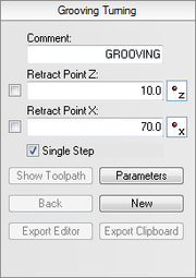
This will open the Grooving Turning pane to the left of the drawing area. Now insert the values shown in the dialog below.
Comment: This comment will be shown in the final NC program. It is always good to include a comment in order to distinguish the various operations in the final program.
Retract Point Z: This is the Z value, to where the operation will retract the tool after completion.
Retract Point X: This is the X value, to where the operation will retract the tool after completion.
The Grooving operation works on a contour, and in order to generate a toolpath we must select that contour. To select the contour for the operation perform the following steps:
Ensure that Single Step is checked in the Grooving Turning pane.
Select the contour shown on the picture below. To do this, start at the far right by selecting the R2 rounded corner with the indication arrow pointing to the left. Now select the next two elements, so the selection looks like the one on the picture below.
Now your drawing should look something like the one below.
Click on the button Parameters in the Grooving Turning pane to open the parameters dialog. Enter the following values into the parameter dialogs shown below.
Cuts Tab
Configures cutting parameters for the operation.
Tool Width: The width of the tool.
Corner Radius: The corner radius of the tool.
Tool Orientation: The two icons indicate how the tool is zeroed.
Stock Clearance: Indicates how far off the part the tool should move before making sideways moves.
Stock Amount: Indicates how much stock there is above the actual groove.
Wall Backoff: If possible, the tool will move this far away from the wall before it retracts.
Angle: This is the angle of the groove's center line. An angle of 90 degrees is a vertical angle on the outside, while an angle of 0 is a horizontal groove from the right.
Direction: This is the direction in which the groove is machined. It can be Positive, Negative, or Bi-Directional.
Stepover: This is the amount of material removed in each cut.
Use Pecking: Indicates weather pecking is used or not.
Pecking Depth: Defines how deep each peck should be.
Pecking Retract: Determines how far the tool should retract between pecks.
Stock to Leave Z: Indicates how much stock should be left in the Z-direction after the whole operation is performed.
Stock to Leave X: Indicates how much stock should be left in the X-direction after the whole operation is performed.
Finish Tab
Configures how the finish passes for the operation should be performed.
Use Finish: Indicates whether or not finish cuts should be performed.
Number of Cuts: Describes how many finish cuts should be taken.
Cut Depth: This is the amount of material that will be removed with each cut.
First Cut Direction: The finish cut is made from both sides. The First Cut Direction is the direction of the first of the finish cuts.
First Distance: This is how far the first cut will be taken along the contour.
Overlap: The second finish cut will overlap the first finish cut by this distance.
Compensation Type: This is the compensation type that is used for the operation. The two most commonly used are Controller or Computer.
After entering the values, close the parameters dialog with OK. To show the generated toolpath on the drawing click on Show Toolpath button in the Grooving Turning pane.
Try experimenting with the various parameters and see how they change the generated toolpath.
Exporting the Toolpath and Backplot in the Editor
Click on Export Clipboard in order to generate the actual program. The program is now in the computer's clipboard and is ready to be inserted into the CNC program.
Change the window to the NC program and move the cursor to the very end by pressing Ctrl+End. Insert the text from the clipboard, either by pressing Ctrl+V, or selecting the icon Paste from the Edit toolbar in the Editor tab.
Now the NC program should look like the following screen.
To verify the generated toolpath, we must simulate it using the integrated Graphical Backplot.
To open the backplot window, click on the Backplot tab at the top of the Ribbon and then on the Backplot Window icon in the File toolbar.
Now a window like the one below will appear.
You can perform another grooving operation in order to machine the groove at the end of the outer thread.