CNC-Calc v6 can generate contour milling toolpaths - with and without radius compensation.
You can watch the related video for this part of the tutorial here:
Creation of Contour Toolpaths
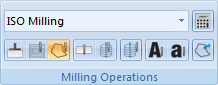
To begin the creation of an NC program for the contour operation, select Contour Milling to generate a CNC-toolpath for contour milling (ensure that ISO Milling is selected in the field File Type).
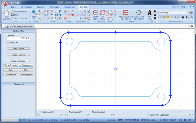
Write the text CONTOUR in the Comment field of the CNC-Calc pane Contour Milling. This text will be included at the start of the final NC code for this operation. When multiple operations exist in the same NC program, the comments will help to locate and identify the start of each operation.
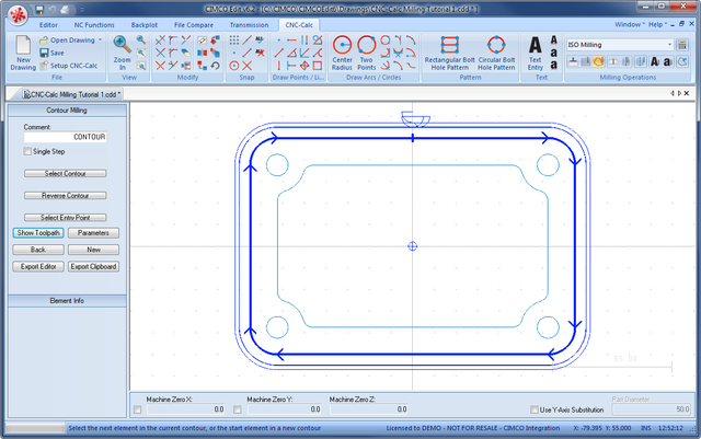
Move the pointer over the outlining contour of the drawing. This highlights the contour element; the arrows indicate the direction the tool will travel. Click on the part of the element that makes the contour direction clockwise like in the picture below.
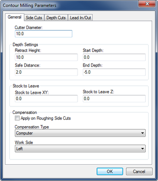
What side the tool will machine is controlled by the Work Side drop-down box on the General tab in the parameters dialog.
Click on the button Parameters in the CNC-Calc pane Contour Milling. This will open the configuration dialog for setting the contour milling parameters.
Enter the values into the Parameters dialogs as shown in the pictures below.
General Tab
This tab contains all the general parameters that are used for roughing and finishing in both depth and side cuts.
Cutter Diameter: The diameter of the tool in use.
Retract Height: The height to which the tool will move between contours, and where it will stop at the end of the operation.
Safe Distance: The distance above the part, where the feedrate will change from rapid to cutting speed.
Start Depth: This is the top of the stock.
End Depth: The depth at which the last cut will be taken. This value is corrected by the Stock to Leave Z value.
Stock to Leave XY: The amount of stock that is left in the XY/side direction at the end of the operation (after both Roughing and Finishing).
Stock to Leave Z: The amount of stock that is left in the Z/depth direction at the end of the operation (after both Roughing and Finishing).
Apply on Roughing Sidecuts: If this option is checked, the compensation type will be applied to both roughing and finishing side cuts. Otherwise computer compensation is used for roughing cuts, and the selected compensation type for finishing cuts.
Compensation Type: This is the compensation type used for the operation.
Work Side: This field determines on which side of the contour the tool will pass. Together with the selected direction of the contour it determines if the milling type will be climb or conventional.
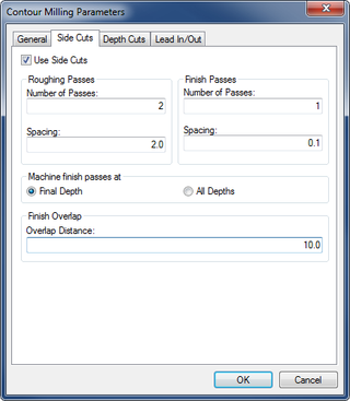
Side Cuts Tab
Configures the cuts taken in the XY direction.
Use Side Cuts: If this option is checked, the operation will perform the cuts defined by the parameters. Otherwise, only one cut at the final contour will be performed.
Number of Passes (Roughing Passes): The number of roughing side cuts in the operation.
Spacing (Roughing Passes): If more than one roughing pass is taken, this is the distance between them.
Number of Passes (Finish Passes): The number of finishing side cuts in the operation.
Spacing (Finish Passes): The distance of each finishing pass.
Final Depth: If this radio button is checked, the finishing passes will only be taken at the final depth.
All Depths: If this radio button is checked, the finishing passes will be taken at every depth.
Overlap Distance: The distance that all the finishing laps will overlap, in order to smooth the surface.
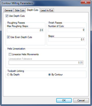
Depth Cuts Tab
Configures the cuts taken in the Z direction.
Use Depth Cuts: If this option is checked, the operation will perform the cuts defined by the parameters. Otherwise, only one cut at the final depth will be performed.
Max Roughing Steps: The maximum cut that will be taken in a roughing cut.
Use Even Depth Cuts: If this option is checked, all the roughing passes will have the same distance. If it is left unchecked, cuts will be taken at the Max Roughing Steps distance, and any rest material will be taken with the last cut.
Number of Cuts: The number of finishing depth cuts in the operation.
Steps: The distance of each finishing pass.
Linearize Helix Movements: Some machines cannot make helix movements, and if this option is checked, all helix movements will be converted to lines in the NC operation.
Linearization Tolerance: When the helix is converted to lines, this will be the maximum error for the final lines.
By Depth: This is only used if multiple contours are milled in the same operation. If selected, the cut on each depth will be performed on all contours, before any cuts are made at a new depth.
By Contour: If selected, one contour will be milled from start to finish, before the next contour is worked upon.
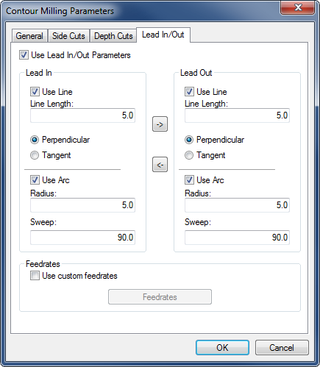
Lead In/Out Tab
Configures the way the tool will approach the contour at the start/end of the roughing, and for each finishing pass.
The use of lead in/out is optional, when the compensation is set to computer or none. It is however mandatory, when any compensation is performed by the controller.
Use Lead In/Out Parameters: Enables or disables the lead in and out.
Use Line: Enables or disables the lead in/out lines.
Line Length: The length of the lead in/out line.
Perpendicular: If this option is selected, the line will be perpendicular to the following element for lead in, and the previous element for lead out.
Tangent: If this is selected, the line will be tangent to the following element for lead in, and the previous element for lead out.
Use Arc: Enables or disables the lead in/out arcs.
Radius: The radius of the lead in/out arc.
Sweep: The sweep angle of the lead in/out arc.
The two arrows in the middle of the dialog are used to copy all values from lead in to lead out, and vice versa.
Use custom feedrates: Check this option to enable using custom feedrates for the milling operation.
Feedrates: Click this button to open a new window to enter custom values for Cutting (XY), Helix/Ramp, and Plunging (Z) feedrates.
Now, close the parameters dialog with OK. To show the generated toolpath click on Show Toolpath button in the Contour Milling pane.
Click on the button Export Clipboard. The NC operation is now in the clipboard, and it is ready for insertion.
Change the window to that of the NC program and press Ctrl+End to move to the very end of the file. Insert the text from the clipboard, either by pressing Ctrl+V, or selecting the icon Paste from the Edit toolbar in the Editor tab.
The NC program in the Editor now consists of two operations, and currently they are both made with the same tool. Now we need to insert a new tool for the contour operation. See next section to know how to insert a tool using the Feed and Speed Calculator.