 |
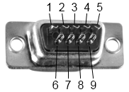 |
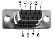
Diagram for DE-9 female connector |
Diagram for DE-9 female connector |
|
|
|
Diagram for DE-9 female connector |
Diagram for DE-9 female connector |
The following table shows the signals of a 9 pin RS-232.
| Pin | Signal | Name |
| 2 | Received Data | RX |
| 3 | Transmitted Data | TX |
| 4 | Data Terminal Ready | DTR |
| 5 | Signal Ground | GND |
| 6 | Data Set Ready | DSR |
| 7 | Request To Send | RTS |
| 8 | Clear To Send | CTS |
|
Only signals used for regular RS-232 communication are shown. |
 |
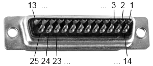 |
Diagram for DB-25 male connector |
Diagram for DB-25 male connector |
This table shows the signals of a 25 pin RS-232 connector. There are 25 connections in the complete specification, but it is very likely to find less than half of these in a given interface.
| Pin | Signal | Name |
| 3 | Received Data | RX |
| 2 | Transmitted Data | TX |
| 20 | Data Terminal Ready | DTR |
| 7 | Signal Ground | GND |
| 6 | Data Set Ready | DSR |
| 4 | Request To Send | RTS |
| 5 | Clear To Send | CTS |
|
Only signals used for regular RS-232 communication are shown. |