 |
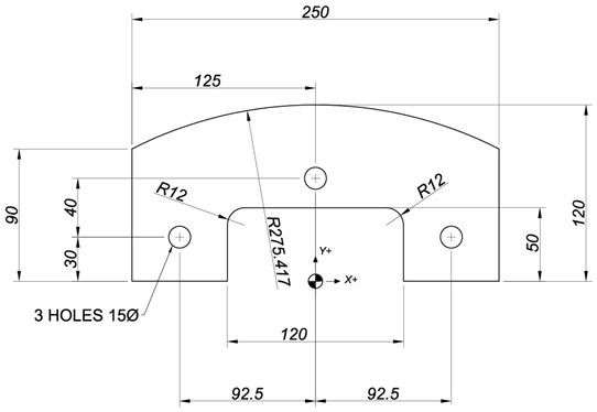
The part below is to be milled on the outside using a 20mm Carbide End Mill and three holes are to be drilled 15mm diameter. Create a profile for the outside from the editor by entering the coordinate end points for X and Y using the relevant G codes. The programming zero and axis directions are shown by the shaded circle.
After creating the coordinates and testing them you will apply Radius Compensation and use Solid Animation to see that the Radius Compensation programming is correct. After the profile, program the drilling of the three holes with a G81 Drilling Cycle.
|
To be able to work on this Milling Exercise the student should have completed all the exercises in the general milling manual ******. Working through the exercises here will assist students to become competent in programming profiles and drilling holes and testing their programmed entries with the graphic backplotting from the Cimco Editor. A large percentage of practical machining on CNC machines requires a programmer to be able to understand the code for these straightforward operations.
In the cases below please use the incremental I, J, K, method of stating arc centres for circular interpolation. It is possible to use the Radius designation for circular moves up to 180 degrees, but in the cases below we suggest that the student becomes familiar with the incremental method.
Launch the CIMCO Edit, go to the Edit Tab, click New. Make sure you have selected ISO Milling in the Editor tab. Start entering the coordinates from a start point of X-25 Y0. The part is symmetrical and commence the profile in a clockwise direction from the left-hand side of the 120mm slot at X-60. Y0. Then continue with the outside contour. Use the NC-Assistant to enter the coordinates as indicated below.
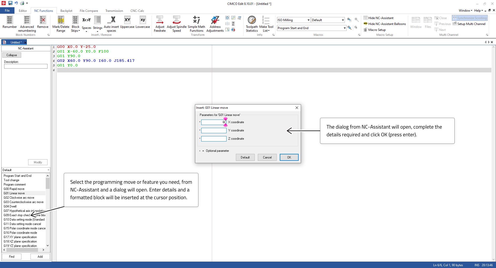 |
When you think you have finished the profiles then test with the back plotting feature. Select the Backplot tab.
 |
Your coordinates will Backplot like this when you have them listed correctly. If not, then check your entries for errors until it does.
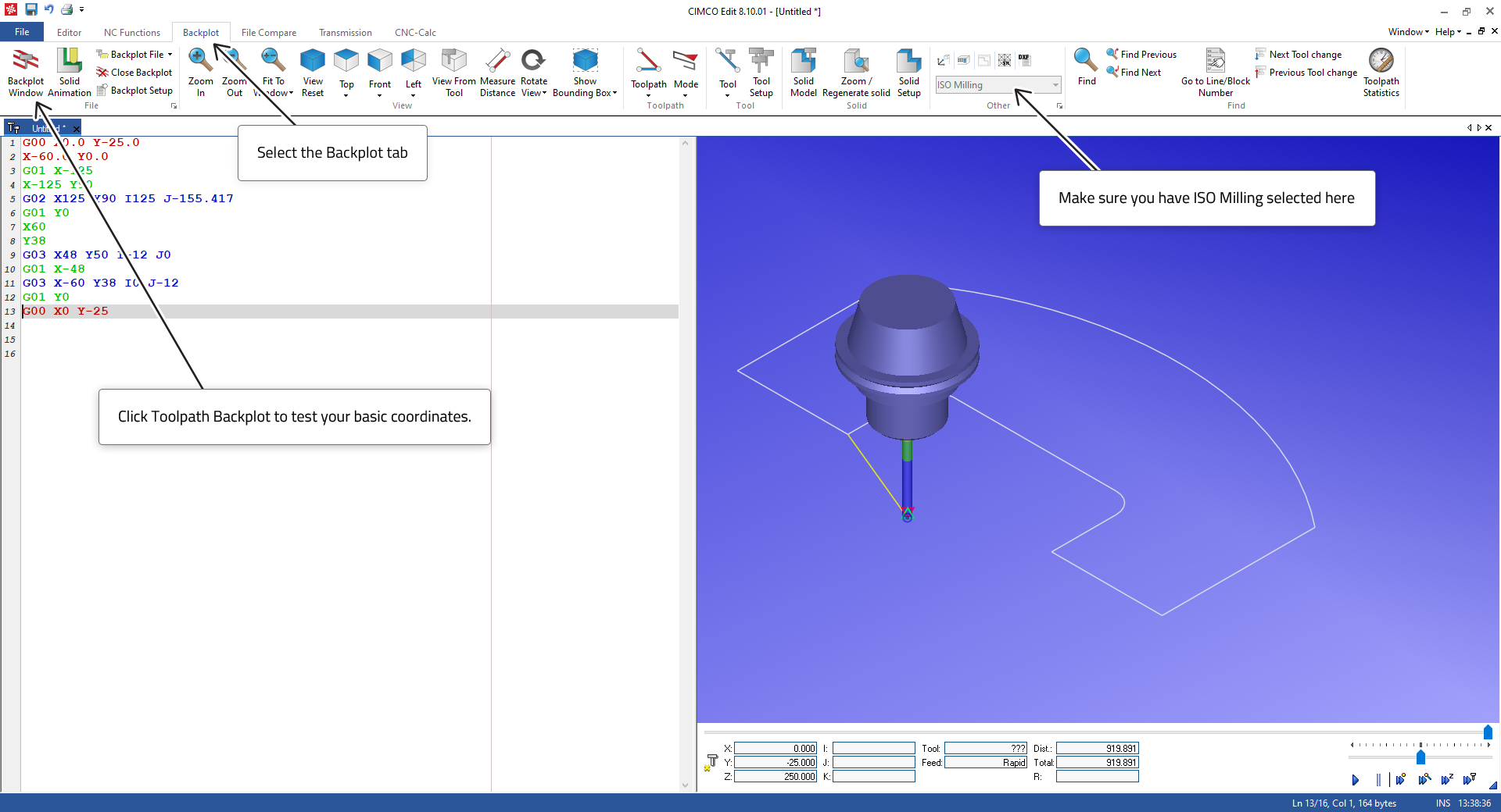
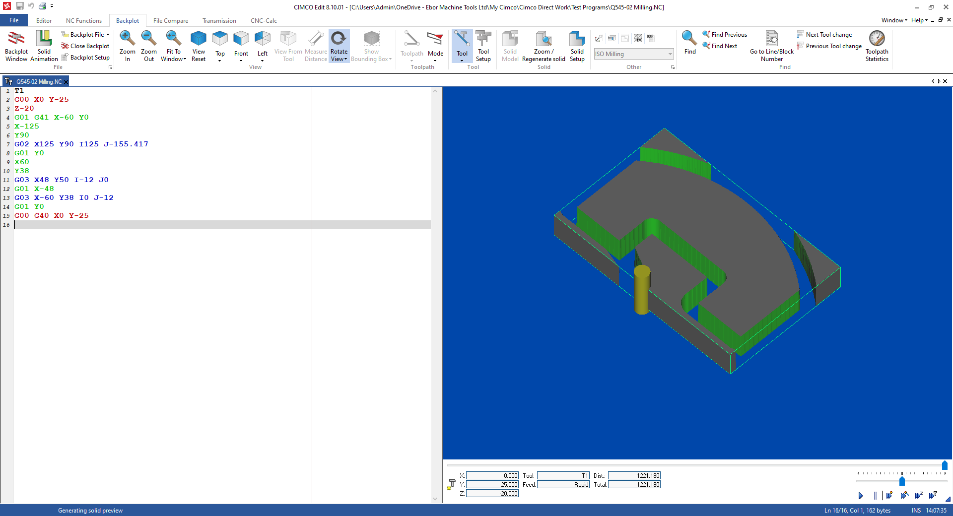
Once you have a true profile, we can assign a Tool, we can then use the solid animation to see if the tool radius compensation is working and correct. So, add T1 to the top of the program and the Radius Compensation code G41 (Left in the direction of travel) and G40 to cancel at the last move leaving the contour. Note that you will need to edit in some Z axis moves to take the tool up and down and additional move to take the tool back to a safe position when machining is finished.
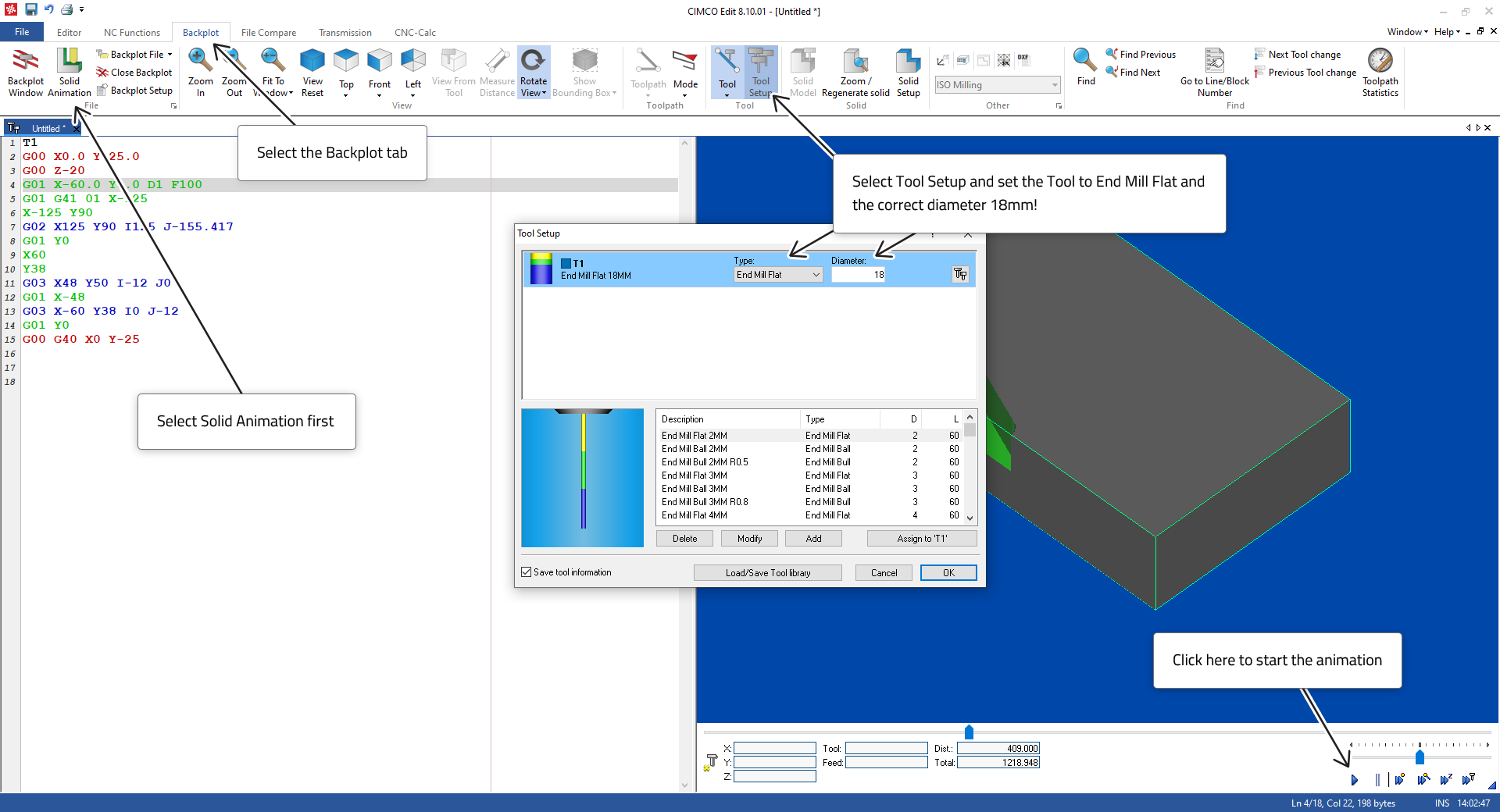 |
When the program is correct, the Solid Animation will look like the image below. The shape of the solid block can be adjusted by clicking on Solid Setup.
 |
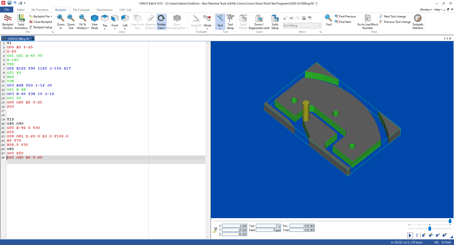
Now we can add the Drilling. So, leave a space in the program and enter the drilling coordinates. After the first coordinate is stated then on the next line select the G81 macro from NC-Assistant and complete the entries.
This will activate the drilling cycle at the first coordinate position and after every move to a new coordinate position until the code G80 is read which will cancel the drilling cycle.
Add a Tool and some Z axis moves to take the Tool up and down. Don’t forget to go to Tool Setup and set the tool to the correct diameter and type. The X, Y coordinates for the first hole can be on the same line as the G81. It is not required for them to be separate, but will work as set out here below. Continue until your Solid Animation looks like the image below.
 |
Continue with the next milling exercises to test your ability to program contour shapes and drill holes.