 |
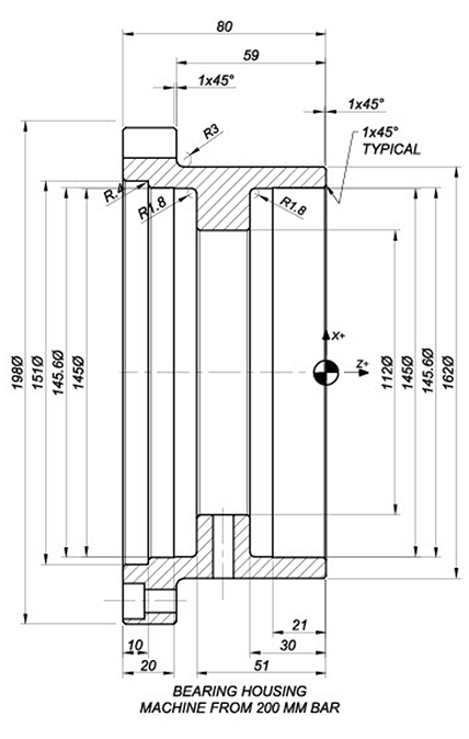
The Bearing Housing shown below is made from a 200mm Bar cut to 100mm long.
Use CIMCO Edit to create a facing operation followed by a rough turning operation on the outside diameter. The programming zero will be from the front face as the drawing is shown and on the centerline.
Remove 3mm on the facing operation when programming this from end. We will then use a G71 Fanuc turning cycle to rough turn the outside profile leaving 1mm on the X diameter and 0.15 on the Z-axis face. Use the same G71 for roughing the bore and finally use G70 for finishing the bore. Use an 80mm UDrill for Opening up the bore.
|
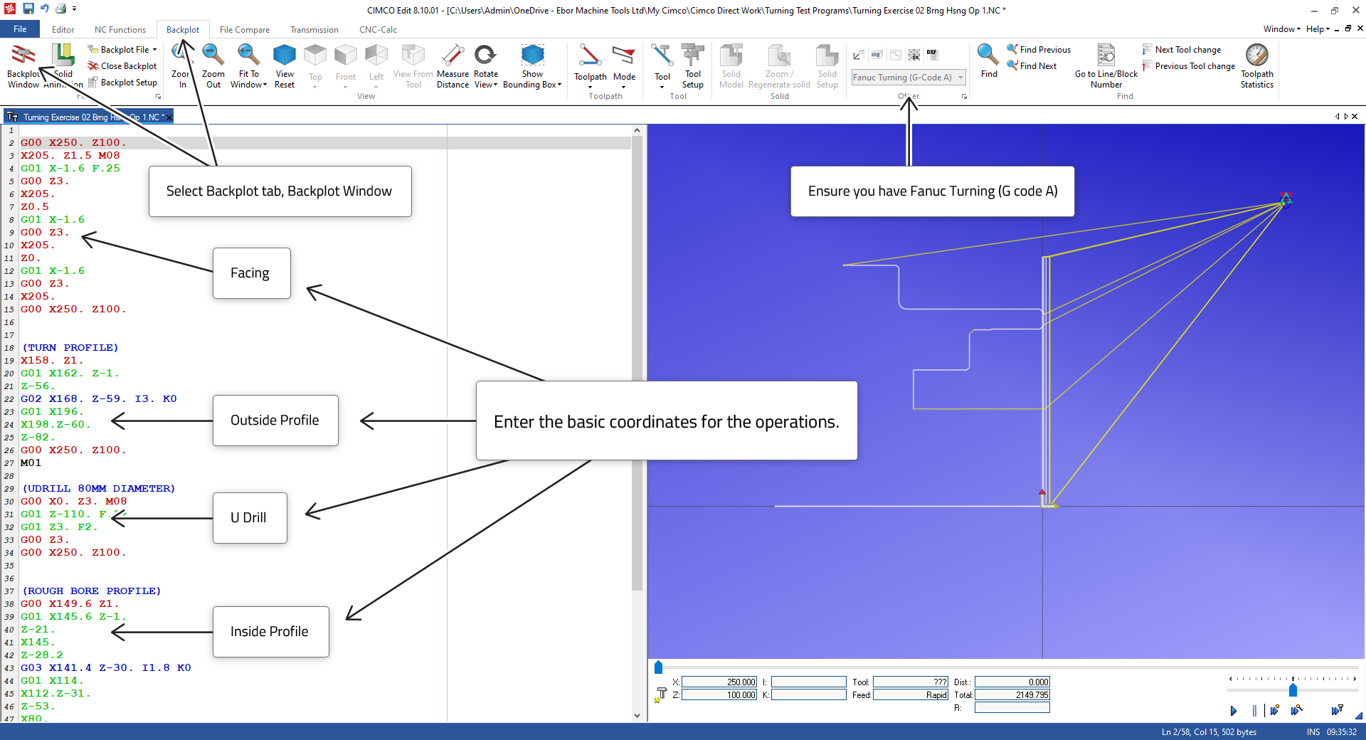
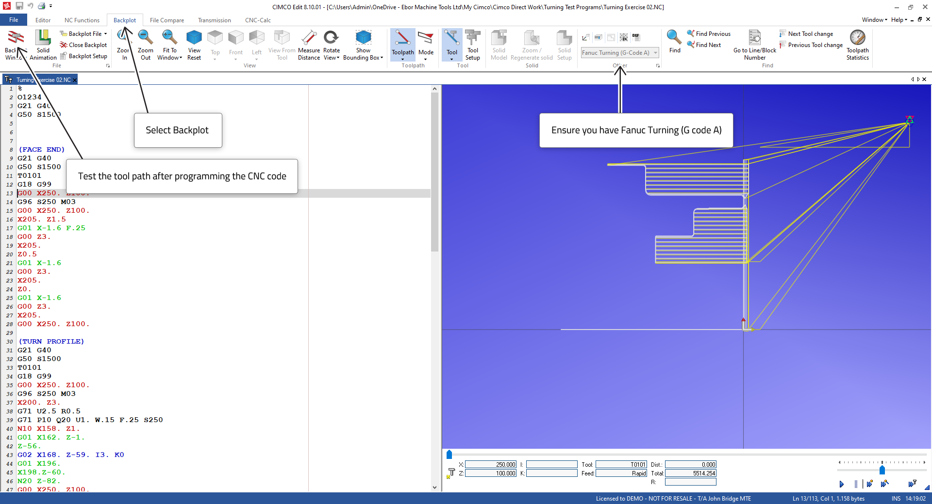
Enter the operations section by section and test the validity of your programming with the toolpath Backplot.
Begin with the facing operation coordinates, then the OD Profile coordinates, then the drilling coordinates and then the Bore Profile coordinates.
Test your coordinates with the toolpath Backplot. To test an individual section of the program, highlight the section and run the toolpath Backplot.
 |
When you are satisfied with the profiles add the G71 Roughing Cycle for outside and inside using the NC-Assistant to open the entry macro. Make sure to position the tool in the correct place to commence the cycles. Add the block numbers to indicate the start and end of profiles as required by the G71 cycle.
 |
Now that you have proven that the profile coordinates and cycles are working, we need to add additional features to make a complete and working program. The program with explanations of individual blocks can be seen below.
In principle the programming should ensure that each tool can be run in automatic as a complete program. The requires we add the following:
1. Each tool requires a header section for setting up the tool change call from a safe place to avoid collision
2. Tool selection and offset activation
3. Spindle information
4. The coordinate information e.g., work shift, (G54).
In this example we are assuming G54 work shift is a default so is not shown.
After the header will be the section containing the machining information and coordinate movements etc. Finally, an end section is required to move the tool away from the part, to stop the program if checking is required, to turn off the spindle and the coolant. So, to summarise each tool needs the following sections.
1. Header
2. Machining
3. End section or Tool change section
We will use I and K coordinates for programming incremental arc centres with G02/G03 circular interpolation moves. It is possible to program using R radius for moves up to 180 degrees with G02/G03 circular moves. R will cover most turning applications and in practice you may wish to program with R. We chose to use incremental I and K arc centres to familiarise students with signed coordinate programming. See previous exercises on G02/G03
| % | |
| O1234 | Program Number |
| G21 G40 | Reset mm/cutter rad compensation. |
| G50 S1500 | Fix Max Spindle Speed |
| (FACE END) | |
| G00 X250. Z100. | Move to safe position |
| T0101 | Call Tool and Offset |
| G96 S250 M03 | Start Spindle CCS 250m/min. |
| X205. Z1.5 M08 | Move to Start Position turn on Coolant. |
| G01 X-1.6 F.25 | 1st Cut. |
| G00 Z3. | Move Tool away from face |
| X205. | Return to start |
| Z0.5 | move over to next Cut. |
| G01 X-1.6 | 2nd Cut |
| G00 Z3. | Move Tool away from face |
| X205. | Return to start |
| Z0. | move over to next Cut |
| G01 X-1.6 | Finish Cut |
| G00 Z3. | Move Tool away from face |
| X205. | return to outside diameter |
| G00 X250. Z100. | move to safe position |
| M01 | Option Stop to check machining, will normally stop the spindle and coolant. Will only stop when the Option switch is set on the CNC control. |
| (TURN OD PROFILE) | |
| G21 G40 | |
| G50 S1500 | |
| G00 X250. Z100. | |
| T0101 | |
| G96 S250 M03 | |
| X200. Z3. M08 | |
| G71 U2.5 R0.5 | Click on G71 Cycle in NC-Assistant and fill in details to insert this line and the next |
| G71 P10 Q20 U1. W.15 F.25 S250 | |
| N10 X158. Z1. | Start of Profile |
| G01 X162. Z-1. | |
| Z-56. | |
| G02 X168. Z-59. I3. K0 | |
| G01 X196. | |
| X198.Z-60. | |
| N20 Z-82. | End of Profile |
| G00 X250. Z100. | |
| M01 | |
| (UDRILL 80MM DIAMETER) | |
| G21 G40 | |
| T0303 | |
| G18 G99 | |
| G00 X250. Z100. | |
| G97 S600 M03 | Start Spindle at fixed speed. |
| G00 X250. Z100. | |
| X0. Z3. M08 | |
| G01 Z-110. F.12 | feed in to machine the hole. |
| G01 Z3. F2. | use a high feed rate to move out – G00 rapid, could be used but might be too fast |
| G00 Z10. | |
| G00 X250. Z100. | |
| M01 | |
| (ROUGH BORE PROFILE) | |
| G21 G40 | |
| G50 S1500 | |
| G00 X250. Z100. | |
| T0404 | |
| X82. Z2. M08 | |
| G71 U2.5 R0.55 | Click on G71 NC-Assistant and fill in details to insert this line and the next |
| G71 P30 Q40 U1. W0.15 F.25 S150 | |
| N30 X149.6 Z1. | Start of Profile |
| G01 X145.6 Z-1. | |
| Z-21. | |
| X145. | |
| Z-28.2 | |
| G03 X141.4 Z-30. I1.8 K0 | |
| G01 X114. | |
| X112.Z-31. | |
| Z-53. | |
| N40 X80. | End of Profile |
| G00 Z10. | |
| G00 X250. Z100. | |
| M01 | |
| (FINISH TURN OD PROFILE) | |
| G21 G40 | |
| G50 S1500 | |
| G00 X250. Z100. | |
| T0606 | |
| G18 G99 | |
| G96 S300 M03 | |
| G70 P10 Q20 U0 W0 | Click G70 NC-Assistant to insert this Finishing Cycle using the profile N10/N20. |
| G00 X220. M08 | |
| G00 X250. Z100. | |
| M01 | |
| (FINISH TURN BORE PROFILE) | |
| G21 G40 | |
| G50 S1500 | |
| G00 X250. Z100. | |
| T0808 | |
| G18 G99 | |
| X80. Z2. M08 | |
| G96 S300 M03 | |
| G70 P30 Q40 U0 W0 | Click G70 NC-Assistant to insert this Finishing Cycle using the profile N30/N40. |
| G00 X250. Z100. | |
| M05 | Spindle Stop |
| M09 | Coolant Stop |
| M30 | End of Program and Reset to start |
| % | |
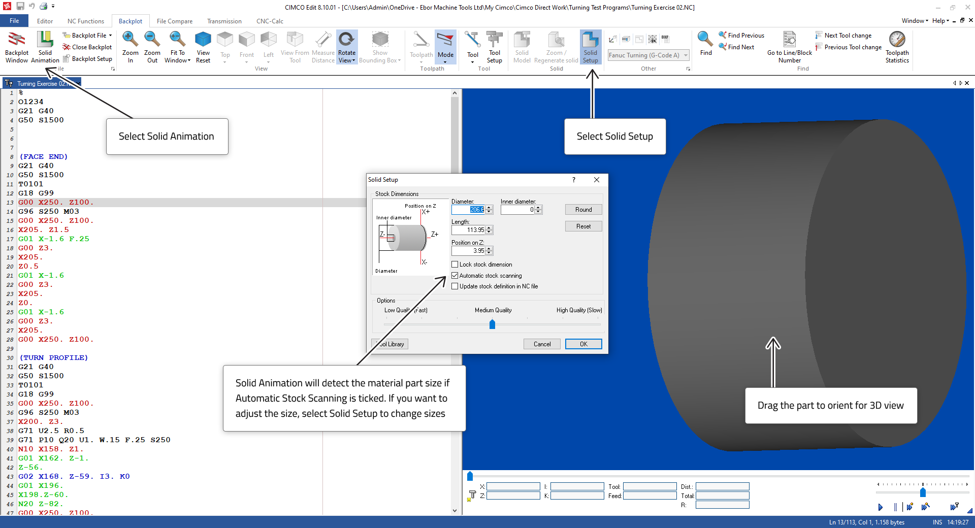
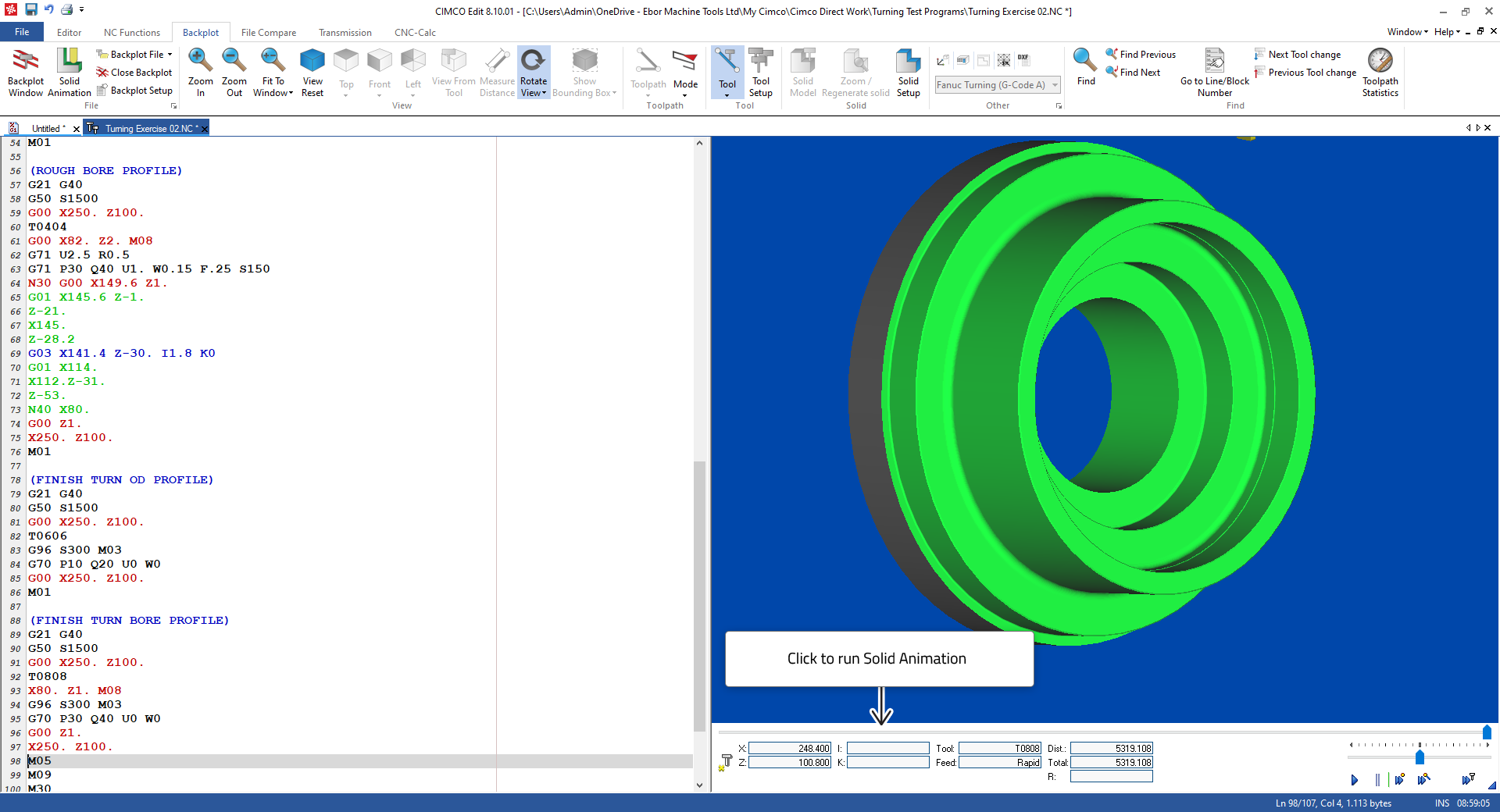
When you are satisfied with you may check your programming with Solid Animation, see below. This first screen shot shows the Solid Setup and how the part Blank size is handled.
 |
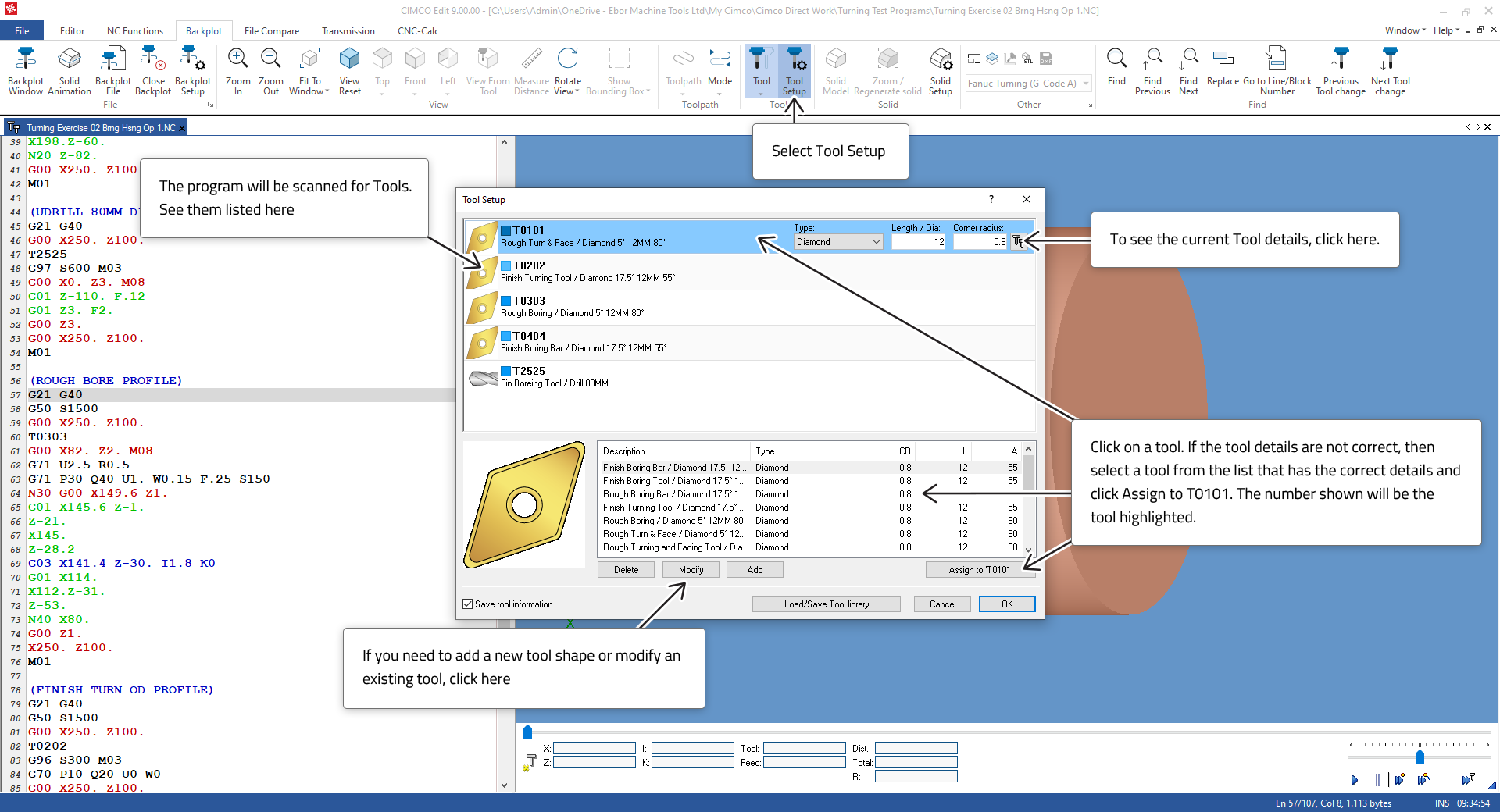
This screen shot below shows how to check and set your tool shapes as the Solid Animation must have the correct Tool shapes as those used on the machine to give a true representation.
 |
When the Blank is set, and the Tool list is correct the Solid animation will give a good representation of the part being machined. The program can be transferred to the CNC control with confidence of its correctness.
 |