 |
|
Normal coordinate system (Milling) |
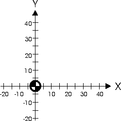
In a CNC program, the workpiece contour must be described so that the toolpaths are defined using points relative to the coordinate system's zero point. This method of describing a profile point by point in 2 axes is called a cartesian Coordinate system. The 2 axes are perpendicular to each other and have a common zero point. Their positive directions are indicated by arrows in the diagram below.
On a normal milling machine, the horizontal line is called the X-axis or the abscissa axis, and the vertical line is called the Y-axis or ordinate axis. The point of intersection is called the zero point and is denoted by a quadrant shaded circle. On a normal Milling Machine, the vertical axis is the Z axis. On a CNC Lathe Z is the horizontal axis and X is the vertical, See the diagram below.
|
|
Normal coordinate system (Milling) |
 |
|
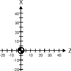
Normal coordinate system (Turning) |
In a cartesian coordinate system, each point can be specified, using numerical values, (coordinates) for the X-axis and the Z-axis, respectively.
On a normal CNC Lathe coordinate system, the Z-axis is horizontal and the X-axis is vertical. The X-axis is usually expressed in diameter. Note: In this example all X-dimensions are expressed in diameter.
 |
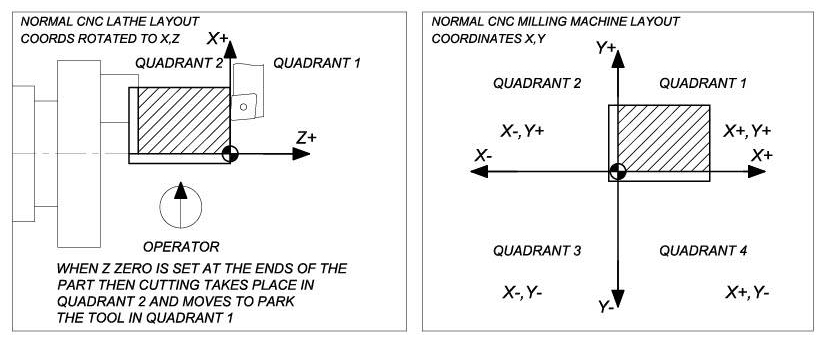
Depending on the construction of the lathe, the coordinate system of X+, Z+ as shown in the figure below, generally for a slant bed lathe construction or mirror-inverted coordinate system for a flatbed lathe with a tool post at turret at the front on the machine.
 |
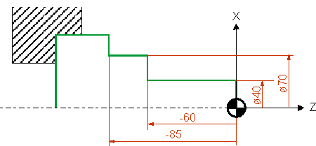
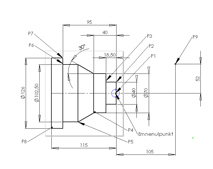
Write the X and Z coordinates from the drawing below. The X measurements are written as diameter measurements.
| P1 | X= | Z= |
| P2 | X= | Z= |
| P3 | X= | Z= |
| P4 | X= | Z= |
| P5 | X= | Z= |
| P6 | X= | Z= |
| P7 | X= | Z= |
| P8 | X= | Z= |
| P9 | X= | Z= |
 |