 |
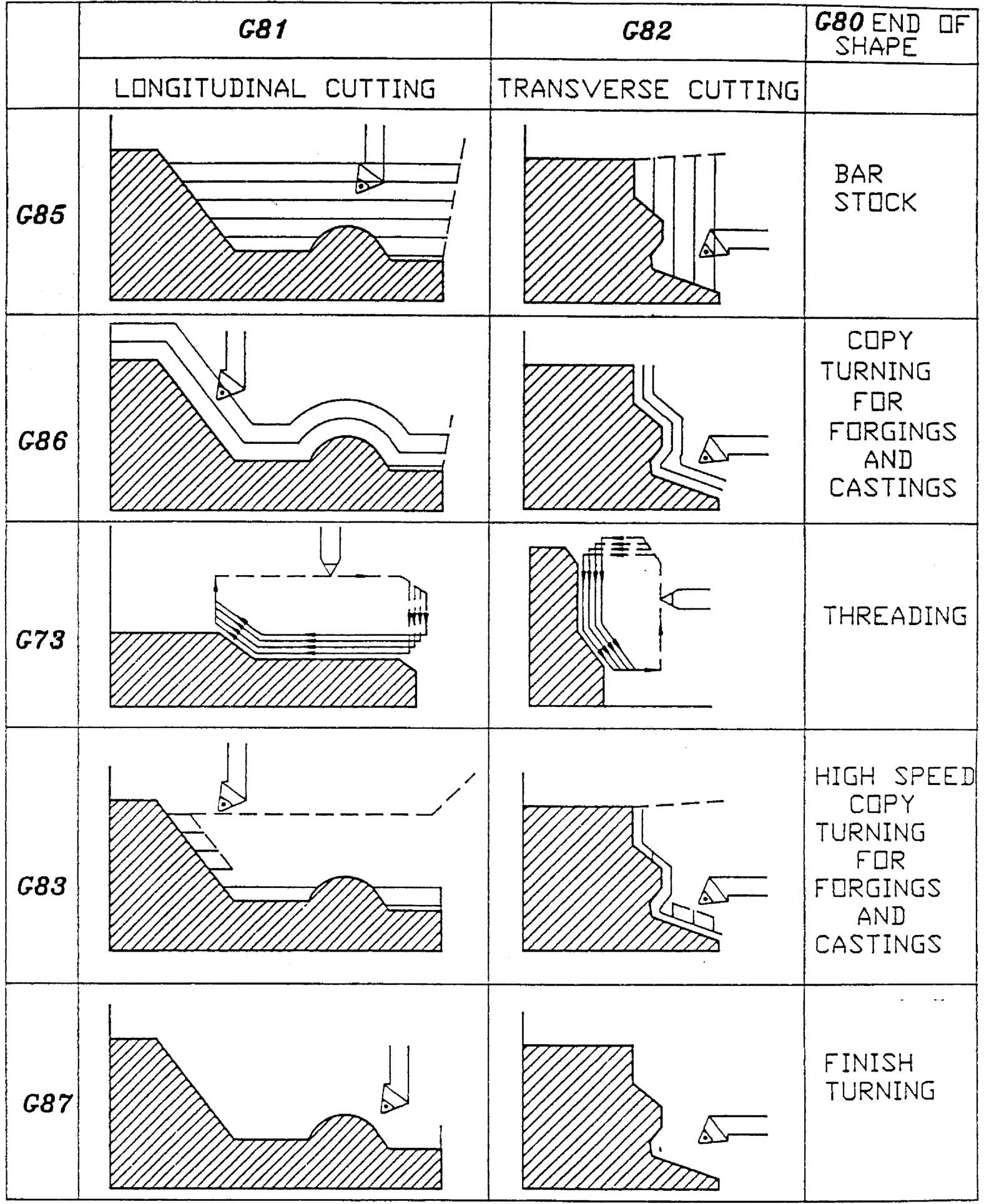
Lathe Auto-Programming (LAP) makes full use of the control’s high-speed processing capability. With this function, the control automatically generates a toolpath to produce the required part contour.
In this function, dimension data of the final contour to be finished, including rough cut conditions, is prepared as the Contour Definition Program; when it is called out with the cutting conditions specified, the control automatically generates the toolpath for the roughing cycles and then finishes the work piece to the programmed dimensions.
This feature permits the programmer to complete the part program simply by picking up the dimensions specified in an engineering drawing, simplifying programming as well as reducing programming time.
The cutting modes available with the LAP can cope with any type of cutting.
Features of LAP are:
1. No special programming language is needed. Normal programming techniques are used for LAP.
2. Programming preparation time can be greatly reduced.
3. Programming for the roughing cycle can be eliminated, and this simplifies manual calculations required for programming.
4. Change of cutting conditions such as depth of cut and feed rate is possible during the roughing cycle.
5. By entering the blank work piece shape, unnecessary air-cutting toolpaths can be eliminated to improve cutting efficiency (LAP4).
|
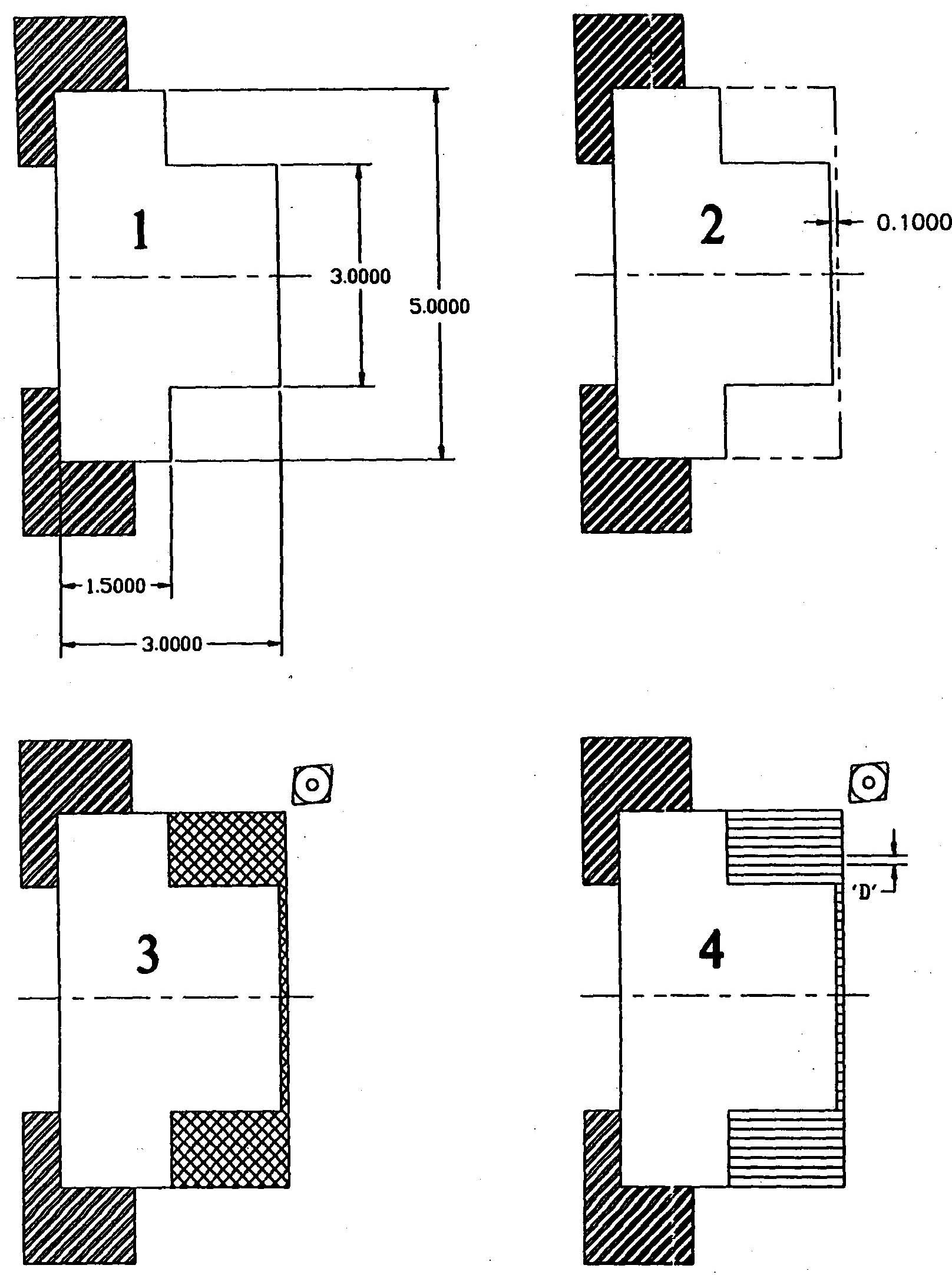 |
| D |
Depth of cut in rough cut cycle. |
| DA |
Depth of cut after rough cut conditions change point A |
| DB |
Depth of cut after rough cut conditions change point B |
| FA |
Feedrate after rough cut conditions change point A |
| FB |
Feedrate after rough cut condition chnge point B |
| E |
Feedrate in rough cut cycle along finish contour |
| XA |
X coordinate of rough-cut condition change point A |
| XB |
X coordinate of rough-cut condition change point B |
| ZA |
Z coordinate of rough-cut condition change point A |
| ZB |
Z coordinate of rough-cut condition change point B |
| U |
Stock removal amount in X-axis direction for finish cut cycle |
| W |
Stock removal amount in Z-axis direction for finish cut cycle |
| H |
Thread heigh in G88 thread cutting cycle. |
| B |
Tip point angle of thread cutting tool in G88 |
Note 1: The following parameters should be specified in incremental values.
D, DA, DB, U, W and H
Note 2: D, DA, DB, XA, XB, U and H parameters should be specified in diameter.
Note 3: In a thread cutting cycle using the M73 pattern, “H-U” must be greater than or Equal to D: H - U > D
In the M74 and M75 patterns, it must be positive: H – U > 0
Note 4: When more than one alphabetic character is used in succession, the control interprets the expression as a variable. Therefore, it is necessary to use a comma as a delimiter for extended address characters: DA=, DB=, FA=, FB=, XA=, XB=, ZA=, and ZB=
Program Example:
GR850
N10 G00 X500 Z800
N20 G50 S4000
N30 T030303
N40 G95 G96
N50 G00 X102 Z5
N60 G85 NLAP1 D5 F-.30 U1 W1
NLAP1 G81
N70 G00 X0 Z5
N80 G01 G42 Z0
N90 G75 X60 L5
N100 Z-25
N110 G03 X80 Z-35 L10
N120 G01 Z-60
N130 X100 Z-75
N140 X102
N150 G40
N160 G80
N170 G00 X500 Z800
N190 M02
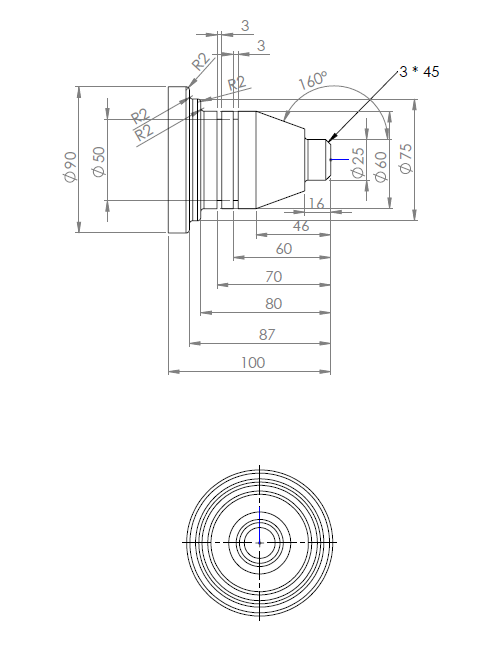
Write a program using the roughing cycle G85 for the part shown below.
 |
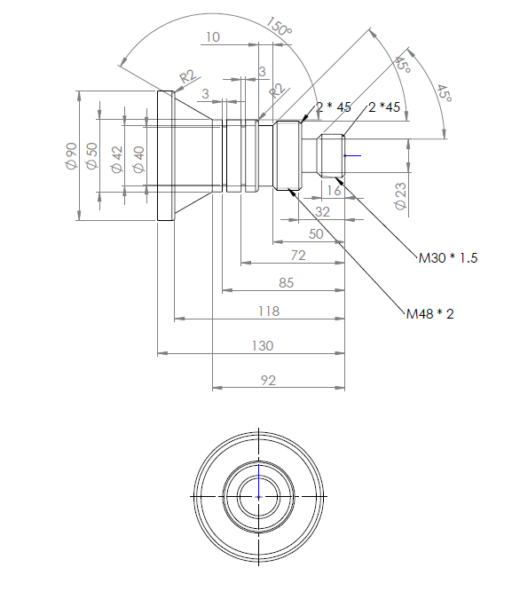
Write a program using the G73 cycle for Threading the part shown below.
 |