 |
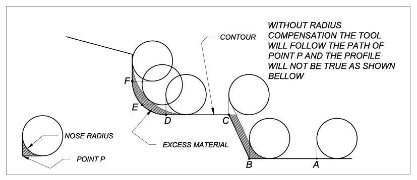
When setting up the tool offsets so that the tool will machine accurately on diameter and length the tool is set to the tangent of the radius of the tool tip in the X and Z axes. When machining a taper or a radius the profile will not be accurate unless tool nose radius compensation is activated. (see diagrams below)
When nose radius compensation is active, the control continuously calculates the real contour path so that shape errors do not occur. The CNC control needs to have further data to be able to correct the path to produce an accurate profile. It should be noted that when the control is calculating the compensated path, the quadrant must be specified for each tool tip. The quadrant of tool operation is usually stated with a location code in tool offset table.
|
 |
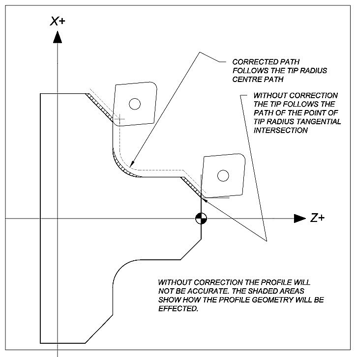
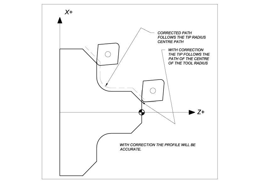
To achieve an accurate profile using a tool with a tip radius, compensation must be applied to correct the toolpath. The dotted line in the diagram below shows the corrected path needed to produce a precise shape. This path is the programmed path offset by the amount of the Tool Radius.
If radius compensation is not applied, then the resulting profile produced will be as though the tool had a sharp point, and it will be seen in the diagram that the chamfers and radii will be incorrect and not complying with the finished part dimensions. The CNC control will need to know what quadrant to tip is in and this can be stated in the location code in the tool offset table. The drawing shows the Tool is operating in quadrant 2 = X+, Z-
 |
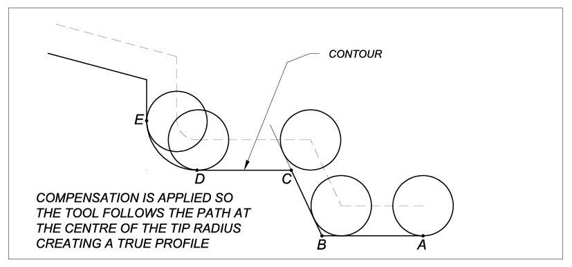
With radius compensation activated the tool will now follow the tool radius centre point path (see below).
 |
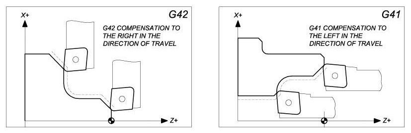
The CNC control will also need to know which side of the path the compensation is to be applied. This is indicated in the programming by the code G41 compensation to the Left and G42 compensation to the right. See below.
 |