 |
|
Figure 5.4: G81 Simple Drill Cycle |
Canned cycles are special codes that act like a macro. They are used for hole making and allow one compact block of code to command many moves. For example, a hole can be created using a peck drill cycle with two lines of code (left column) whereas the same move would require maybe twenty or more lines of code if each motion was commanded separately (right column).
|
Canned Cycle |
Equivalent Motion: Expanded Code |
|
N70 G98 G83 X1. Y1. Z-1.04 R0.06 Q0.15 P0 F9. N75 G80 |
N70 Z0.06 N75 Z0.04 N80 G01 Z-0.19 F9. N85 G00 Z0.06 N90 Z-0.11 N95 G01 Z-0.34 N100 G00 Z0.06 N105 Z-0.26 N110 G01 Z-0.49. N115 G00 Z0.06 N120 Z-0.41 N125 G01 Z-0.64. N130 G00 Z0.06 N135 Z-0.56 N140 G01 Z-0.79 N145 G00 Z0.06 N150 Z-0.71 N155 G01 Z-0.94. N160 G00 Z0.06 N165 Z-0.86 N170 G01 Z-1.04. N175 G00 Z0.25 |
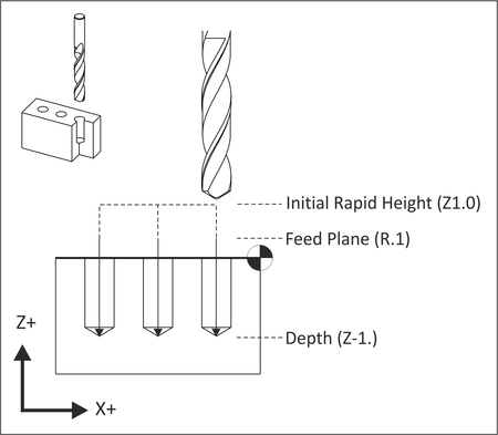
This cycle makes holes by feeding to depth at a programmed feed rate and then retracting at rapid rate. It is accompanied by G98 or G99, XYZ coordinates, feed rate, and R. R is the feed plane and Z is final depth of the tool tip.
All drill cycles are accompanied by G98 or G99 that determine how high the tool retracts between holes.
G0 Z1. G43 H1
G98 G81 X.5 Y.5 Z-1. R.1 F9.5
|
|
Figure 5.4: G81 Simple Drill Cycle |
This cycle is identical to G81 except it includes a dwell value, P (in seconds). P is used to pause the tool feed rate at the final depth to create a clean countersink or counterbore finish.
G0 Z1. G43 H1
G98 G82 X.5 Y.5 Z-.0925 P.1 R0.1 F9.5
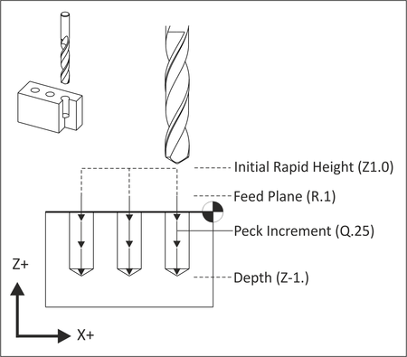
A peck drill cycle is used on deep holes. The tool drills an incremental distance (Q) and then fully retracts from the hole. This breaks the chip, clears material out of the hole, and allows coolant to cool the drill and flush out the hole, reducing the chance of the tool breaking and producing a better quality hole. The simplest form of this cycle is shown in Figure 5.5. Another version of this cycle, called a deep drill cycle , uses I,J,K parameters to reduce the amount of peck as the hole gets deeper.
G0 Z1. G43 H1
G83 X.5 Y.5 Z-1. R0.1 Q.25 F9.
 |
|
Figure 5.5: G83 Peck Drill Cycle |
Most modern machines support rigid tapping, which eliminates the need to use special tapping attachments. Rigid tapping precisely coordinates the spindle speed and feed to match the lead of the thread. It then stops and reverses the spindle at the bottom of the cycle to retract the tap. The parameters for the tap cycle are identical to simple drilling (G81).
G0 Z1. G43 H1
G84 X.5 Y.5 Z-1.5 R0.1 F20.
This code commands the machine to interpret coordinates as absolute position moves in the active Work Coordinate System. All programs are written in absolute coordinates.
G90 G0 X1. Y1.
This code commands the machine to interpret coordinates as incremental position moves. G91 is used by subprograms but most programming done with CAD/CAM software and does not use subprograms.
The only common use of G91 is in combination with G28 to send the machine back to its home position at the end of the program. The machine must be set back to G90 mode in the next block as a safety measure.
G91 G28 Z0.
G90
This code is used in drill cycles to retract the tool to the clearance plane (set in the next previous block) between holes to avoid clamps.
G0 Z1. G43 H1
G98 G81 Z-0.325 R0.1 F12.
|
Figure 5.6: G98 (Return to Clearance Plane) |
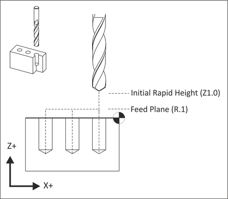
This code is used in drill cycles to retract the tool to the rapid plane (R) between holes. G99 mode is the machine default and is used when clamp clearance between holes is not an issue.
G0 Z1. G43 H1
G99 G81 Z-0.325 R0.1 F12.
 |
|
Figure 5.7: G99 Motion (Return to R-Plane) |