 |
|
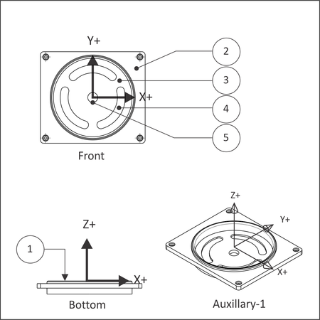
Figure 7.1: Prismatic Part (Orientation in CAD) |
2-½D milling toolpaths machine only in the XY plane. The Z axis is used only to position the tool at depth. The move to the cutting plane is a straight down feed, rapid, ramp or helical feed move.
The term, Prismatic, is a term commonly used in engineering used to describe 2-½D parts. There are, however, prismatic parts that require 4 th or 5-Axis machining, so the term is used in machining only to describe parts where all machined faces lie normal to the machine tool spindle. Because 2-½D is a clumsy term this book uses Prismatic and 2D interchangeably to describe parts just described, on a CNC mill with three controllable axes (XYZ). The XY axes are normal to the machine spindle and Z is used only to position the tool to depth (either in a feed or rapid motion).
Figure 7.1 shows a prismatic part. All machined features lie parallel to the XY plane. Each Z-level can be machined by positiong the tool at a fixed Z-level and then moving the XY axes to remove material. machining. Every feature can be reached with the tool approaching either from the Front or Bottom views. There are several cutting planes in this example, including the model top (1), top of the face where the holes start (2), the bottom of the pocket (3) where the slots begin, the bottom of the slots (4), and the bottom of the hole through the center (5).
|
|
Figure 7.1: Prismatic Part (Orientation in CAD) |
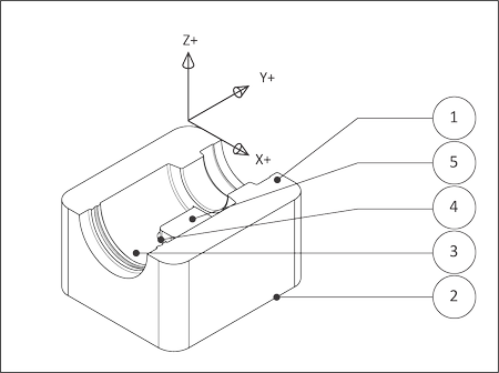
3D refers to non-prismatic parts, including molds and complex organic shapes. Most consumer goods, for example, include 3D features. Figure 7.2 shows half of a stamping die. This part is typical in that it includes both 3D and 2D features. The 2D features are the top face (1) , and the outside contour (2).
3D features, like the revolved surfaces (3) and fillet (4), require more complex machine motion. The revolved surfaces require XZ tool motion. The fillet requires XYZ tool motion. Even the flat (5) and cavity roughing (though technically planar) require 3D toolpaths because the adjacent revolved surfaces and fillet must be considered to prevent gouging the part. The calculations required to calculate these toolpaths are highly complex and the subject of the Chapter 9: 3D Toolpaths.
 |
|
Figure 7.2: 3D Part |
4th axis toolpaths require an auxiliary rotary axis 4th installed on the CNC machine parallel to either the X or Y-axis. 4th axis toolpaths fall into two categories: 4th Axis Substitution and Simultaneous 4th Axis.
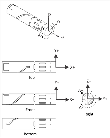
Axis substitution paths are illustrated in Figure 7.3. The most common setup is with the rotary axis mounted parallel to the CNC X-axis. With axis substitution machining, the tool axis centerline always points towards the centerline of the rotational axis (no Y-motion) when milling. The tool feeds to depth (Z) and then only up to two axes can move at once (X-A) to make the feature.
The name "substitution" comes from how these paths were defined before CAD was widely used. Geometry was draw flat (XY) and then the Y-axis values were converted to A-rotational values, based on the cylinder radius. In other words, the flat geometry was "wrapped" around a constant diameter cylinder.
 |
|
Figure 7.3: 4th Axis Substitution (X-A) |
Simultaneous 4th axis machining allows all 4 axes to move at once (XYZA). This type of motion is very complex and is actually a sub-category of Simultaneous 5-axis machining. 5th Axis parts require all 5 machine axes to move at once (XYZAB).
Simultaneous 4th and 5th axis machining is beyond the scope of this course.