 |
|
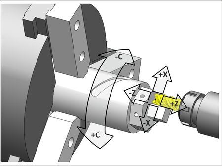
Figure 8.6: Driven Tool Machining |
One variation of the CNC lathe is called a Mill-Turn center. In the milling mode, the spindle becomes a rotary axis that can stop, index, or move in sync with the other axes to create shapes including face milling, radial holes and slots. For example, Figure 8.6 shows a face milling operation. The X-C axes are coordinated to move the tool in a square shape on the part face.
|
|
Figure 8.6: Driven Tool Machining |
Mill-Turn centers can reduce production costs and make it easier to machine high tolerance parts compared with making the part on two different machines.
There are many configurations of mill-turn lathes, including machines with two tool turrets, two spindles, and even 5-axis milling. These can be challenging to program manually, but the CNC control includes functions to make programming easier. Many CAD/CAM systems support mill-turn centers, though the more exotic the machine configuration, the more difficult it may be to properly simulate and automatically generate edit-free G-code files using CAD/CAM.