 |
|
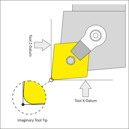
Figure 8.7: Imaginary Tool Tip |
The corners of lathe tools are radii. The imaginary tool tip is where vertical and horizontal lines tangent to the cutting edge of the tool intersect. This point is found by touching off the tool in the Z and X directions on the part or using a tool probe.
Because the imaginary tool tip can be found with great precision, it is used to control the tool. That is, all the Z-X coordinates in the G-code program are in reference to this point. Tool positions are easy to calculate parallel to the machine axes, but more complex for arcs and chamfers.
However, since almost everyone programs using CAD/CAM software or an on-control programming utility, you won't have to calculate complex lathe tool paths. The programmer inputs the part profile geometry, and the control or software does all the calculations. Let the CAD/CAM software or control do this work.
|
|
Figure 8.7: Imaginary Tool Tip |
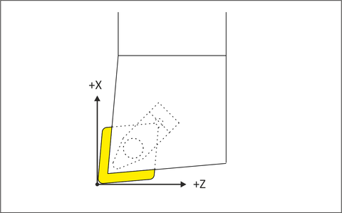
When programming a lathe, think in terms of motion of the imaginary tool tip. As shown in Figure 8.8, more positive Z-values move the tool to the right. More positive X-values move the tool away from the part.
 |
|
Figure 8.8: Tool Motion |