 |
|
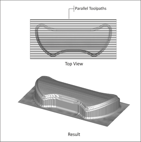
Figure 9.6: 3D Parallel Tool Path |
The goal of 3D finishing tool paths is to remove material left by roughing paths and produce a part that meets design requirements for dimensional accuracy and surface finish.
A commonly used finish path is Parallel, shown in Figure 9.6. Parallel gets its name because, when viewed from above, tool paths appear parallel to each other.
|
|
Figure 9.6: 3D Parallel Tool Path |
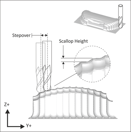
Parallel tool paths calculate quickly and are reliable. However, they usually require additional finish passes to clean up heavy scallops (cusps).
Scallops can be seen Figure 9.7 and are most prominent on the closest wall. Small tool path step over values produce smaller scallops. Notice how scallop height changes depending on the topography of the part.
Parallel tool paths tend to produce large scallops on steep walls roughly parallel to the path direction. As the tool steps to the next pass, the path drops down farther in Z on these walls compared with flat areas of the part. One approach to machining away these scallops is to create an additional parallel finish path rotated 90 degrees to the first. Of course this increases total program run time substantially.
 |
|
Figure 9.7: Scallop Height |