 |
|
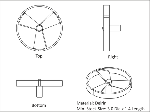
Figure A.19: Project-7, Fan |
This project teaches the following skills:
|
|
Figure A.19: Project-7, Fan |
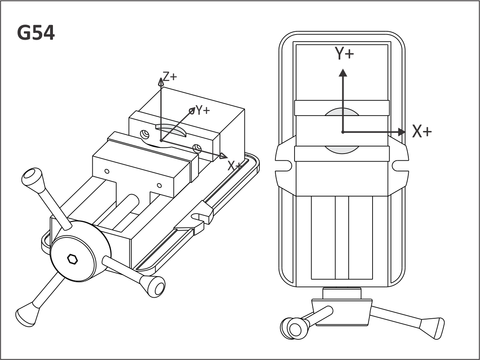
Cut a pocket into the aluminum jaws as shown in Figure A.20. This is used to grip the sawed raw stock while machining the top side (G54).
Soft jaws for this part require advanced planning. Round stock is usually slightly larger than the size ordered, so either first turn it down on to the desired size on a lathe, or cut the jaws to match the actual material size. The jaws have to be cut deep enough to grip the part securely during machining. Cutting forces in Delrin are small, so a grip depth of .30 inches is adequate to secure this part.
 |
|
Figure A.20: Job-1 Soft Jaws |
The XY datum is established by the pocket machined into the jaws. In other words, soft jaws both grip and set the datum for the part.
Before machining the jaws, place a bar (a vise hard jaw works well) between the vise jaws about 2.00 inches wide. This stabilizes the jaws during machining and sets the grip width.
One way to find the approximate location of the pocket center is to mark the center of the stock with a pencil, and set the stock on the top of the jaws. Load a small drill in the tool holder and jog the machine over the XY center of the stock and set this as the G54 X0Y0 position.
Machine the pocket using a spring pass to ensure the walls are straight. De-burr the top edge of the pocket by creating a .05 in chamfer.
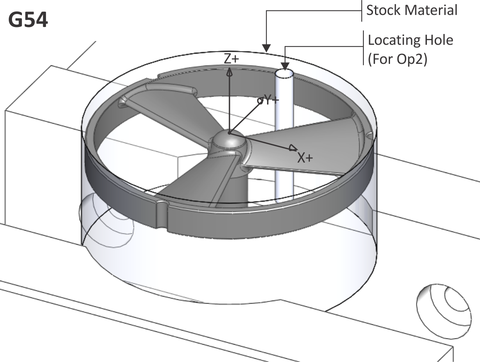
It is safest to shift the G54 Z upward so all rapid moves are +Z values. Because sawed stock varies in length typically by .02-.05 in, set the G54 position to the top surface of the shortest stock material to be machined.
Tighten the jaws firmly with a toque wrench, or mark the vise handle location after closing so the vise can always be tightened to the same pressure. Machine the blade using the processes in Table A.6.
|
Fan: Job-1 Setup | ||||
|
| ||||
|
G54 Datum: XY Same as soft jaw pocket center. Set G54 about .01 in below the top of the shortest length of sawed stock. | ||||
|
Op-1 Face |
Tool (inch) .375 End Mill |
Speed (rpm) 4100 |
Feed XY (ipm) 40. |
Feed Z (ipm) 20. |
|
Finish part to thickness. Use light cuts to prevent part from being pulled out of vise. Include enough rough passes to accommodate the tallest piece of stock to be machined. | ||||
|
Op-2 Drill |
Tool (inch) .125 Drill |
Speed (rpm) 4600 |
Feed XY (ipm) N/A |
Feed Z (ipm) 18. |
|
Drill the three holes around the perimeter of the fan ring, and the locating hole for Op2. The locating hole will be used to set the part orientation for Job 2 so that the top and bottom fan blades surfaces match precisely. | ||||
|
Op-3 3D Rough |
Tool (in) .188 (3/16) End Mill |
Speed (rpm) 8100. |
Feed XY (ipm) 80. |
Feed Z (ipm) 40. |
|
Rough the outside and inside surfaces of the fan ring to a depth of Z-.40. Leave stock of .005 on all surfaces. | ||||
|
Op-4 3D Finish |
Tool (in) .125 (1/8) Ball Mill |
Speed (rpm) 8. |
Feed XY (ipm) 8. |
Feed Z (ipm) 4. |
|
Pre-finish the inside surfaces of the fan to remove all scallop steps. Use a spiral or circular path and a stepover of .09. Leave .005 stock on all surfaces. | ||||
|
Op-5 3D Finish |
Tool (in) .093 (3/32) Ball Mill |
Speed (rpm) 10,000 |
Feed XY (ipm) 75. |
Feed Z (ipm) 30. |
|
Finish the inside surfaces of the fan. Use a spiral or circular path and a stepover of .01. | ||||
|
Op-6 3D Pencil |
Tool (in) .093 (3/32) Ball Mill |
Speed (rpm) 10,000 |
Feed XY (ipm) 75. |
Feed Z (ipm) 30. |
|
Pencil mill the inside surfaces to remove any scallops remaining on the inside corners. Use a stepover of .01 in. | ||||
|
Op-7 2D Contour |
Tool (in) .188 (3/16) End Mill |
Speed (rpm) 8100. |
Feed XY (ipm) 80. |
Feed Z (ipm) 40. |
|
Finish the OD of the part to a depth of Z-.4. | ||||
|
Op-8 2D Chamfer |
Tool (in) .25 Center Drill |
Speed (rpm) 6000. |
Feed XY (ipm) 24. |
Feed Z (ipm) 12. |
|
Create the chamfers on the top of the ring. Use line/arc lead in/out and take two passes. | ||||
Replace the soft jaws with new blanks or re-cut the previous jaws. Set up and cut the jaw pockets for Job-2 exactly like for Job-1. De-burr the top edge of the pocket by creating a .01 in chamfer.
These jaws include a .125 in diameter hole used to set the rotary index position of the part for the second operation. This hole should extend about .25 in into the soft jaw step.
 |
|
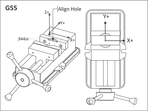
Figure A.21: Soft Jaws for Job-2 |
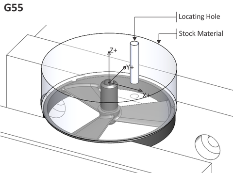
Set the G55 Z Position off the floor of the soft jaw pocket, then shift it upward .944 in above this surface (distance from face of fan ring to bottom of the part).
|
G55 Z could be set to the face of the soft jaw pocket as long as the top face of the ring is set as the G55 datum in the CAM system. Just be sure to set the clearance, rapid, and feed heights so the tools clear the part and stock during machining. |
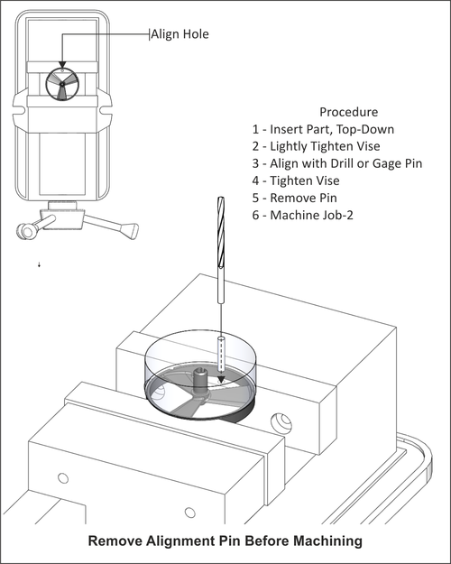
Lightly tighten the vise jaws so part still rotates in fixture.
Next, insert a .125 in diameter gage pin (or a 1/8 in drill upside-down) through the locating hole in the stock (drilled in Job 1), and into the hole in the fixture. Use this to align the part so the surfaces machined in Job 1 line up perfectly with the surfaces machine in Job 2. Securely clamp the jaws. Remove the pin or drill before machining.
 |
|
Figure A.22: Use Drill or gage pin to Align Part |
Machine the bottom of the fan using the operations listed in Table A.7. Select the appropriate tools and machining parameters.
|
Fan: Job-2 Setup | |
|
| |
|
G55 Datum: XY Same as soft jaw pocket center. Set G55 from bottom of pocket to top of finished part (Z+.994 inches). | |
|
Op-1 Face |
Finish part to thickness. Use light cuts to prevent part from being pulled out of vise. |
|
Op-2 Drill |
Peck drill hole in center of spindle. |
|
Op-3 3D Rough |
Rough the bottom of the part leaving stock for finish passes. |
|
Op-4 2D Contour |
Finish the OD of spindle. |
|
Op-5 3D Finish |
Pre-finish the bottom blade surfaces leaving stock for finish machining. |
|
Op-6 3D Finish |
Finish the bottom blade surfaces. |
|
Op-7 2D Contour |
Use a ball mill to machine the slot in the spindle. |
|
Op-8 2D Contour |
Finish the bottom of the blade shroud. |
|
Op-9 3D Pencil |
Pencil mill to remove scallops in the fillets between the blades and housing and spindle. |
|
Op-10 Chamfer Mill |
Create the chamfers on the edges of the housing. |