 |
|
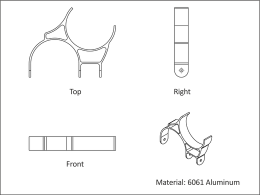
Figure A.32: Project-11, Bracket |
This project teaches the following skills:
Almost every part presents unique work holding challenges. Part geometry, material type, wall thickness, and features all influence work holding.
Parts like this present multiple challenges. Like a chess player, a machinist has to think ahead several moves to visualize what the part will look like each step of the way. Before starting this project, it is important to consider machining methods, sequencing, work holding, and potential problems.
|
|
Figure A.32: Project-11, Bracket |
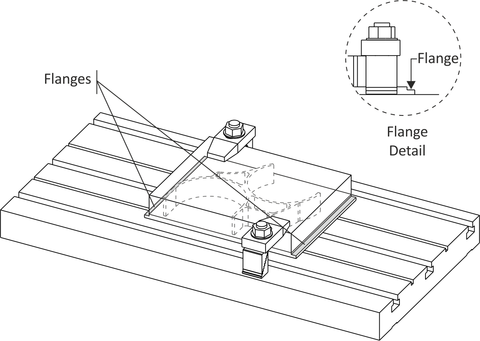
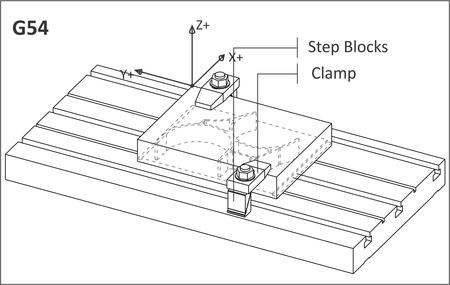
Use clamps to secure the part to the table as shown in Figure A.33 bellow. Flanges will be cut on the ends of the stock to hold and locate the part in subsequent operations. Plan ahead. Use stock thick enough to form rigid flanges and face the part on both sides. Locate clamps clear of tool paths and set rapid heights to easily clear the clamps.
Many styles of clamps are available. The type shown here uses Step Blocks to set the clamp at the same level as the top of stock. Machining on this side of the part produces significant cutting pressures. Because the clamps rest on material that will be later cut away, there is no problem with marring the finished part, so the bolts can be tightened very securely to prevent the part from slipping.
Once the part is clamped to the table, it must not be moved until all machining on this side are complete.
 |
|
Figure A.33: Bracket, Job-1 Setup |
Machine flanges on the part ends as shown in the figure in Table A.15. These flanges serve two purposes. The first is to grip the part while the top side is machined. The second is to level the part when machining the left and right sides.
|
Bracket: Machine Flanges | |
|
| |
|
Op-1 Contour |
Machine flanges. |
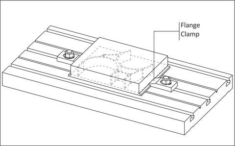
Being careful not to shift the part at all, add clamps to the flanges. Use low profile clamps and plan operations carefully to ensue the tool does not contact the clamps or create excessive cutting pressure that might shift the part.
Use as many clamps as necessary to secure the part. Many styles and size of clamps are commercially available, or you can fabricate your own. Most cutting pressure is in the XY plane, though the plate must be held against the table to prevent the part from bending as material is removed. Test to see if the part has lifted after machining by trying to slide a piece of notebook paper or feeler gauge between the table and part bottom. If the flange is thick enough and the clamping is good, the part will lie flat against the table after machining the top.
 |
|
Figure A.34: Install Flange Clamps |
Face, pocket, and finish this side complete. Cut the perimeter of the part .010 inches below the profile to ensure no flashing remains after the bottom side of the part is faced off in the last operations.
|
Bracket: Job 1 | |
|
| |
|
Datum: Same as part datum. | |
|
Op-1 Face |
Face part. |
|
Op-2 2D Contour |
Rough and finish OD of part. Machine at least .005 below the bottom profile. Avoid clamps. |
|
Op-3 |
Rough and finish pockets. |
An angle plate is a sturdy precision ground plate that is used to set parts on edge.
The next operation machines the holes and fillets on the right side. (This is done before finishing the bottom so the material helps support the part from bending while machining the ends.)
Bolt and align the angle plate to the table. Secure the part with toggle clamps and use a Machinists Square to level the part. Check by running a dial indicator across the flange as shown. This angle is critical, so make the part as level as possible.
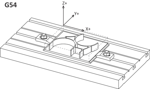
The XY Datum can be found by picking up the reference point shown in Figure A.35. Notice that the Y-datum is established by locating the finished part top against the angle plate.
 |
|
Figure A.35: Angle Plate Setup |
Carefully machine (or cut on a band saw) the part stock as shown in Figure A.36 to provide tool clearance for the next operations. Use light cuts because heavy cuts could cause the part to shift. The edge being cut away is thin and not firmly supported -a situation prone to resonance. If the tool starts to chatter, slow feed rate and spindle speed.
The setup shown here is a tradeoff between tool clearance and work rigidity. The less the part hangs off the angle plate the more rigid the setup, but this reduces tool clearance needed to machine the radii.
As always, do not run the program unless certain the setup is stable and safe. Use the simulation and collision checking features of the CAD/CAM software and check for tool and holder interference with the remaining stock and angle plate.
|
This part is a good illustration of the difference between prototype and production manufacturing. Large production quantities might justify the cost of more complex fixtures that would allow the part to be easily clamped. A rotary 4th axis might be used so that the part could be automatically reposition –eliminating several setups and improving the accuracy of the holes. |
 |
|
Figure A.36: Bracket, Machine Tool Clearance |
Center drill and drill the holes in the ears, and then contour the radii. Take small cuts and use the smallest recommended chip load to prevent tool chatter or deforming the part.
|
Bracket: Job 2 | |
|
| |
|
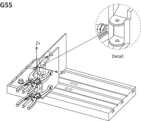
Datum: See Figure 59. G55 XY is corner formed by Job 1. G55 Z is top surface of this flange. | |
|
Op-1 Center Drill |
Center Drill Top Hole. |
|
Op-2 Drill |
Center Drill Top Holes. |
|
Op-3 2D Contour |
Rough and finish top radii. |
Rotate the part 180 degrees about the Y-axis as shown in the figure in Table A.18 below. Use the same procedures as in Steps 5 thru 7 to level the part, find the datum, remove material for tool and holder clearance, and then machine the hole and radius.
|
This is a tricky setup because the piece is flipped, has deformed during machining, and the hole must be located precisely to align with the holes created in the previous operation. Do your best work and check your datum carefully. Scrapping the part at this step would be costly. |
|
Bracket: Job-3 | |
|
| |
|
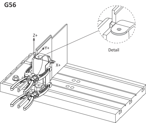
Datum: Pick up G56 XY from corner of flange as in Step 7, Table A.17. | |
|
Op-1 Center Drill |
Center Drill Top Hole. |
|
Op-2 Drill |
Center Drill Top Holes. |
|
Op-3 2D Contour |
Rough and finish top radii. |
Set the part on the table face side down. Clamp in the center as shown in the figure in Table A.19.
|
Bracket: Job 4, Face Ends | |
|
| |
|
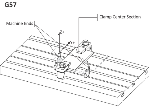
Datum: Set G57 XY as shown. This is the only edge on the part where the XY datum can be set accurately. The XY datum can be set +/- .05 in because this is a facing operation only. Set Z from surface of table to establish part thickness. | |
|
Op-1 Face |
Rough and finish ends of part avoiding clamps. |
Install on the ends of the part as shown in the figure in Table A.20. Place aluminum pads under the clamps so they won't scratch or damage the part. Machine the center section to complete the part.
|
Bracket: Job 4 , Face Center | |
|
| |
|
Datum: Same as Table A.19. | |
|
Op-1 Face |
Rough and finish ends of part avoiding clamps. |