 |
|
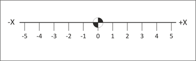
Figure 4.1: X-Axis Number Line |
CNC motion is based on a 3D Cartesian coordinate system.
The basis of this system is the number line marked at equal intervals. The axis is labeled (X, Y or Z). One point on the line is designated as the Origin. Numbers on one side of the line are marked as positive and those to the other side marked negative.
|
|
Figure 4.1: X-Axis Number Line |
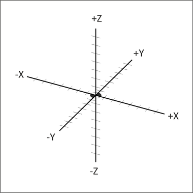
The Cartesian coordinate system consists of three number lines, labeled X, Y and Z, set at 90 degree angles to each other as shown in Figure 4.2 below. The origin, or Datum, is where the three axes cross each other. The labels, orientations, and directions of the Cartesian coordinate system in Figure 4.2 are typical of most Vertical Machining Center (VMC).
 |
|
Figure 4.2: 3D Cartesian Coordinate System |
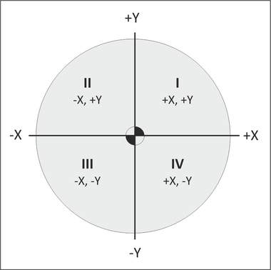
Any two axes form a plane. Planes are named by the axes that define them. For example, Figure 4.3 shows the XY plane, which is the primary work plane for machining on a VMC. A plane can be divided into four quadrants, labeled I, II, III and IV with axes designations as shown in the illustration below.
 |
|
Figure 4.3: Quadrants |
CNC Programs can be written in either Inch or Metric units. The machine can be switched with a single code to accept either.
In the United States, most programming is using inch units because most tooling is in inches and machinists are more familiar with the inch measurement system. Even if the part is designed in metric, it is usually converted to inch units for machining and metric tools are used only when no inch equivalent is available (for example when creating metric tapped holes).
Table 4.1 lists the units and maximum precision for inch and metric data used by CNC machines.
|
Units and Precision | ||||
|
Data Type |
Inch Units |
Metric Units | ||
|
Coordinate |
inches | .0001 |
mm | .001 |
|
Speed |
rev/min | 1. |
rev/min | 1. |
|
Feed |
in/min | 1. |
mm/min | 1. |
|
Tap Feed |
in/min | .001 |
mm/min | .01 |