 |
|
Figure 5.1: G0 Dogleg Motion |
This code commands the machine to move as fast as it can to a specified point. It is always used with a coordinate position and is modal. Unlike G1, G0 does not coordinate the axes to move in a straight line. Rather, each axis moves at its maximum speed until it is satisfied. This results in "dogleg" motion as shown in Figure 5.1, below.
G0 X0. Y0.
|
|
Figure 5.1: G0 Dogleg Motion |
|
Caution: The rapid speed of some machines can exceed 1. An incorrect offset or coordinate move can crash the machine faster than the operator can hit the emergency stop. Use the rapid feed override on the machine when running a program for the first time. |
This command moves the tool in a straight line at a programmed feed rate.
G1 X1. Y1.1255 F32.
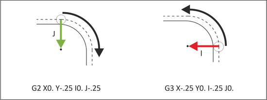
G2 commands clockwise arcs. G3 commands counterclockwise arcs. Arcs must exist on a plane (G17/G18/G19) and include the coordinates of the arc end point and IJK vectors indicating the arc center location.
 |
|
Figure 5.2: G2/G3 Arcs |
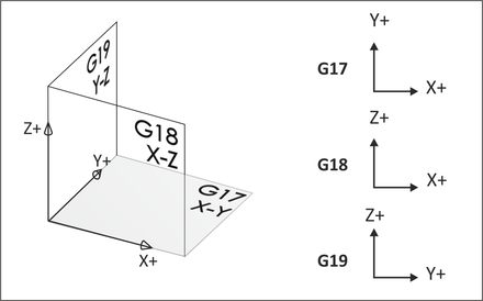
Arcs must exist on a plane designated by the command G17 (XY), G18 (XZ) or G19 (YZ). G17 is the machine default.
 |
|
Figure 5.3: Plane Designations |
CDC is a key to precision CNC machining, allowing the operator to compensate for tool wear and deflection by commanding the machine to veer left (G41) or right (G42) from the programmed path. G40 cancels cutter compensation. The amount of offset is entered in a CNC control D-register. The wear register can be thought of like a table that the control refers to with every move.
| Tool Diameter Offset | Value |
| D1 | 0.0020 |
| D2 | 0.0000 |
| D3 | 0.0000 |
| D4 | 0.0000 |
| D5 | 0.0000 |
| D6 | 0.0000 |
The value in the D-register is calculated by the machine tool operator, who monitors the finished size of part features, compares them with the print, and enters the difference in the register as needed to keep the part within specifications. If there is no deviation, the register is set to zero.
G1 G41 D1 X1.0 Y.25 F36.
G43 activates tool length compensation. It is always accompanied by an H-code and Z-move, where H is the tool length offset (TLO) register to read, and Z is the height to go to in reference to the part datum.
The (TLO) can be thought of like a table on the control:
| Tool Length Resister | Z |
| H1 | 12.6280 |
| H2 | 6.3582 |
| H3 | 9.7852 |
| H4 | 6.8943 |
| H5 | 10.5673 |
| H6 | 7.1258 |
The TLO is combined with the active fixture offset on the control so the machine knows where the tip of the tool is in relation to the part datum. The process for finding the TLO is detailed in Chapter 6: CNC Operation.
G43 H1 Z1.
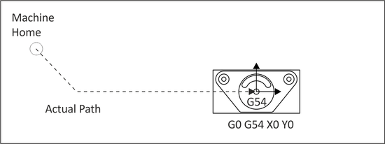
Work offsets are data registers in the CNC control that hold the distance from the machine home X, Y, Z position to the part datum. These offsets can be thought of like a table on the control:
| Work Offset | X | Y | Z |
| G54 | 14.2567 | 6.6597 | 2.0183 |
| G55 | 0.0000 | 0.0000 | 0.0000 |
| G56 | 0.0000 | 0.0000 | 0.0000 |
| G57 | 0.0000 | 0.0000 | 0.0000 |
| G58 | 0.0000 | 0.0000 | 0.0000 |
| G59 | 0.0000 | 0.0000 | 0.0000 |
|
Tip: G54 is usually used for the first machining setup. Additional offsets are used to machine other sides of the part. |
The X and Y values represent the distance from the machine home to part datum XY. The Z value is the distance from the tool reference point (for example, the top of a 1-2-3 block) and the part Z-datum. The process for finding TLO and fixture offset Z is detailed in Chapter 6: CNC Operation.
G54 X0. Y0.