Check List
Buttons
1
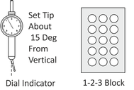
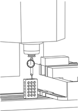
Prepare:
- Ensure tip angle of dial indicator is at about 15 degrees.
- Ensure gauge block is flat on table, no chips underneath, and not floating on coolant.
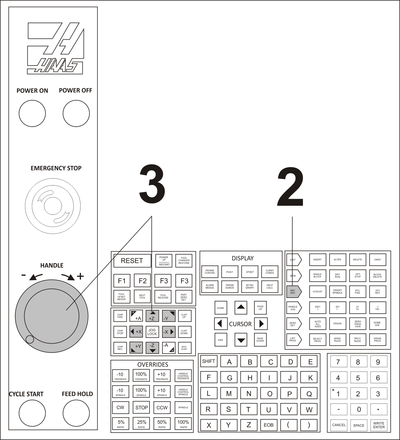
2
MDI Mode: Select
- Ensure machine is in MDI Mode
![]()
3
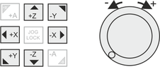
Handle: As Needed
- Select jog direction and use handle as required to place dial indicator stylus on top of gauge block and the dial reads zero.
Note: Machine parameter 64 (T OFS MEAS USES WORK) must be set to OFF to use this method.
4
Posit Button: Press
![]()
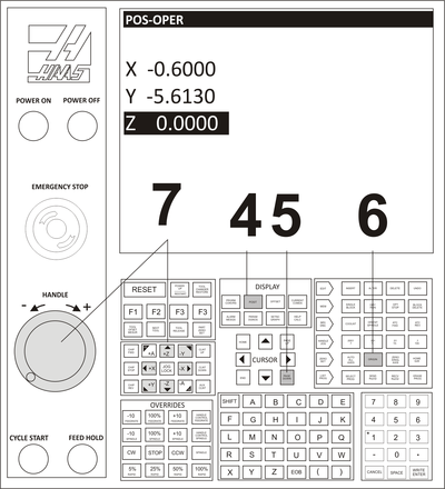
5
Operator Screen: Select
- Use PG DN Button (5 times) until POS-OPER screen appears.
![]()
6
Origin: Set
- Press Origin button to set Z-value on operator screen to zero.
![]()
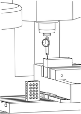
7
Handle: As Needed
- Select jog direction and use handle as required to place dial indicator stylus on top of part stock and the dial reads zero.
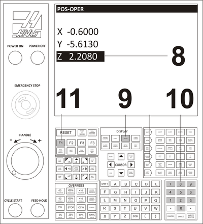
8
Operator Z Value: Read
- Read the operator Z value from the graphic area. This is the incremental distance between the top of the 1-2-3 block and the top of the part. Ex: 2.2080
9
Offset Page: Set G54 Z Value
- Press Offset button twice to get to Offsets Page
![]()
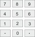
10
Numeric Keypad: Enter Z Value
- Input the value using the numeric keyboard.
- To set Z below the part face, reduce the value by the amount of material removed by the face cut.
11
F1 Button: Press
- Select the F1 button to enter the value input in Step #7 into the Z offset field.
![]()