 |
|
Figure 17: Carbide Insert Designation |
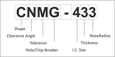
Carbide inserts use a coding system of numbers and letters to describe their shape, dimensions, and important parameters. For example, the designation of the insert shown in Figures 11-16 is a CNMG-433.
|
|
Figure 17: Carbide Insert Designation |
There are at least 18 different shapes of carbide inserts. The most commonly used are shown in Table 8.1 with their letter designation. The angle in this designation refers to the included nose angle at the cutting radius of the tool.
| Designation | Shape | |
| T | Triangle | |
| S | Square | |
| C | 80 degree diamond | |
| D | 55 degree diamond | |
| V | 35 degree diamond | |
| R | Round |
Clearance angle is the draft on the face(s) of the insert that contact material during machining. More about insert angles a little later.
| Designation | Clearance Angle |
| N | 0 Degrees (No Draft) |
| A | 3 Degrees |
| B | 5 Degrees |
| C | 7 Degrees |
| P | 11 Degrees |
This is how much variation is allowed in the dimensional size of the insert. Tolerances described with this parameter include the corner point (nose radius), thickness, and I.C. Typical tolerances are shown in Table 8.3:
| Designation | Cornerpoint | Thickness | I.C. |
| M | .002-.005 | .005 | .002-.005 |
| G | .001 | .005 | .001 |
| E | .001 | .001 | .001 |
| K | .0005 | .001 | .002-.005 |
The hole/chip breaker designation describes both features with one letter. The hole in the insert and tool holder must match. If no letter exists in this field, then the insert does not have a hole to secure it to the holder, and is held by clamp force only.
| Designation | Hole Shape | Chipbreaker Type |
| G | Cylindrical | Single-sided |
| W | 40-60 deg, double c-sink | None |
| R | None | Single-sided |
| T | 40-60 deg, double c-sink | Single-sided |
| P | Cylindrical | Hi-double positive |
| Z | Cylindrical | Hi-double positive |
Inserts are measured by the diameter of an inscribed circle. I.C.'s range from .0625 in to 1.25 in. Table 8.5 lists the sizes you are most likely to use.
| Designation | Decimal (inch) | Fractional (inch) |
| 3 | .375 | 3/8 |
| 4 | .500 | 1/2 |
Insert thickness.
| Designation | Decimal (inch) | Fractional (inch) |
| 3 | .187 | 3/16 |
| 4 | .250 | 1/4 |
Insert cutting nose radius.
| Designation | Decimal (inch) | Fractional (inch) |
| 1 | .016 | 1/64 |
| 2 | .031 | 1/32 |
| 3 | .047 | 3/64 |
The insert shapes, sizes, and designations in these tables are just of few of what is available. Any lathe tool catalog or manufacturers web site will show many more.
It is not important to memorize every tool shape or designation scheme. It is important to know insert terms and specifications to understand insert recommendations from the tool representative or technical resource to select the correct insert for the application.