 |
|
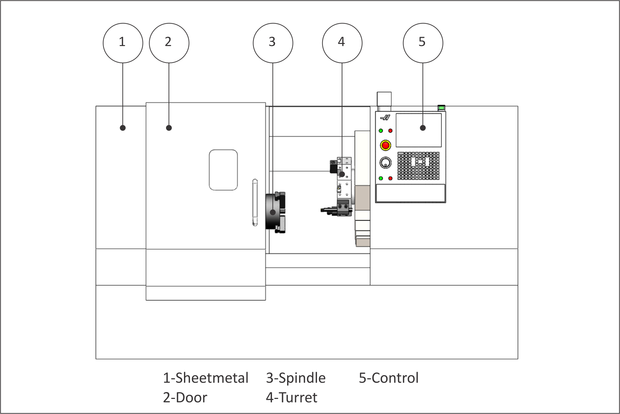
Figure 8.2: CNC Lathe |
The major components of a CNC turning center are shown in Figure 8.2.
|
|
Figure 8.2: CNC Lathe |
Protective housing that contain cutting chips and capture coolant for recycling.
The door is closed during operation. Lathes can be dangerous if the part is thrown or a tool breaks during machining. The window is made from a special high impact glass. The lathe should not be operated if this glass is cracked.
The spindle is attached at one end the machine drive system. The other end attaches the chuck, which grips the part.
The turret holds and moves the tools. Tools are bolted to the turret using a variety of specialized holders, depending on the type of tool. The turret indexes to present the tool to the work piece.
The CNC control used to operate the machine.
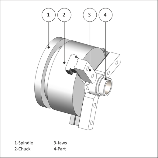
The spindle turns the chuck. The chuck grips the part using hard jaws, soft jaws, or collet. The most common configuration is the three jaw chuck, shown in Figure 8.3. The chuck requires air pressure to open and close the jaws, and set the gripping force. Pressure must be high enough to securely hold the part, but not so great as to deform fragile parts.
 |
|
Figure 8.3: Spindle Detail |
Tool holders bolt to either the front or perimeter of the turret. Tool changes are made by the machine indexing the turret to place the appropriate tool closest to the part.
The method by which the tools are attached to the turret, and the direction the tool faces in relation to the part, vary depending on the tool, operation, and cut direction. For example, a facing tool is oriented radially to the part, to maximize tool rigidity and work envelope. A boring bar is oriented axially to allow the bar to enter and exit the bore.
 |
|
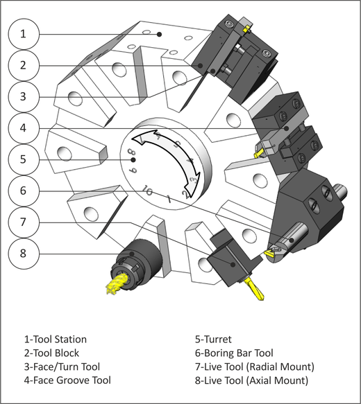
Figure 8.4: Turret Detail |
The turret is divided into stations evenly spaced around the perimeter. Most lathes with tool turrets have about 10 tool stations. Tools are connected to the turret by a tool holder and tool block. The tool holder and block used depend on the type of tool and mount direction.
Tool blocks act as the interface between the tool holder and the turret. They bolt to the face or perimeter of the turret. Different blocks are used depending on the type of tool and orientation.
Turning tools, which includes face, OD rough and finish, groove and cutoff, are usually mounted radially with respect to the part. The cutting tool is usually a ceramic insert mounted in a tool post designed for the specific shape and size insert.
Face groove tools are mounted axially from the part.
The turret holds and moves the tools. To change tools, the turret unlocks, rotates to present the active tool to the work piece, and then locks again. Care must be taken that the turret is away from the part so that none of the tools collide with the part as the turret indexes.
A boring bar is used to create a precision size and finish hole through the bore of the part. These are mounted axially with the spindle
A "live tool" is a tool that rotates, being driven by a mechanism in the holder. Radially mounted live tools are used for cross drilling or milling on the diameter of the part.
Axial mounted live tools mill or drill on the face of the part.