 |
|
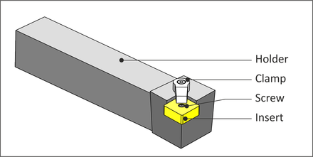
Figure 8.11: Typical Lathe Tool Holder |
While lathes use some of the same tools that mills use, including spot drills, drills, and taps, most turning is done using carbide inserts. Inserts are gripped in holders, which in turn are bolted to the lathe turret (see Fig. 8.4). Figure 8.11 shows a typical insert-holder combination. This is a left-handed holder, because the tool cutting edge points to the left when viewing the holder from the top as shown in Figure 8.12.
|
|
Figure 8.11: Typical Lathe Tool Holder |
Carbide inserts employ highly engineered composite structures, coatings, and geometry features to achieve great accuracy and high material removal rates. Some inserts can be indexed to use other edges when one becomes worn. Inserts are quickly and easily replaced at the machine.
 |
|
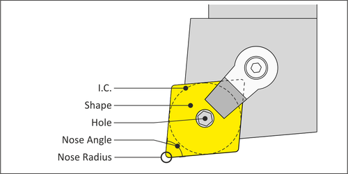
Figure 8.12: Insert Terms |
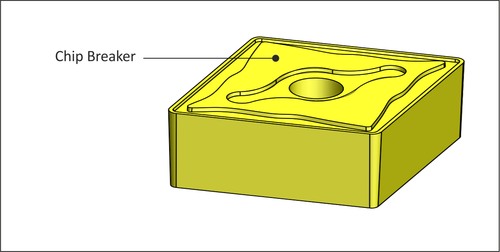
A chip breaker is a feature in the face of the insert that disrupts the flow of chips such that they break into short segments, rather than forming a long, stringy chip.
 |
|
Figure 8.13: Chip Breaker |
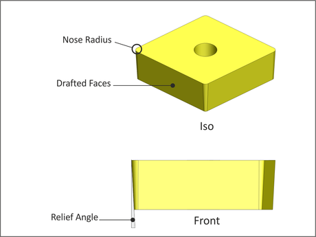
Most inserts have drafted faces on the walls. This is called Relief Angle. Relief prevents the walls of the insert from rubbing against the part.
 |
|
Figure 8.14: Relief Angle |
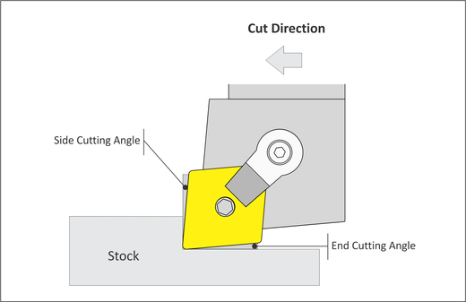
The edge of the tool in the cut direction forms an angle with a line perpendicular to the cut direction. This is called Side Cutting Angle. The angle formed by the trailing edge and parallel to the cut direction is called the End Cutting Angle.
The purpose of these angles is to provide proper clearance between the tool and work piece. For example, the 80 degree insert shown in Figure 8.15 is rigid and has enough side and end cutting angle for facing and rough turning operations. However, complex contours may require a 55 or 30 degree insert to provide tool side and end clearance for the tool and holder. Very steep or vertical walls may require a round or slot tool to carve.
 |
|
Figure 8.15: Cutting Angles |
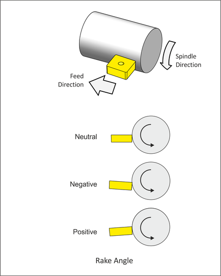
Rake angle is set by the tool holder. Rake angle helps control the direction of the chip and cutting pressure. Angle is measured from face of the insert to the Z-X plane of the machine.
 |
|
Figure 8.16: Rake Angle |